Cooling system for a farm machine

a technology for cooling systems and farm machines, applied in the direction of stationary tubular conduit assemblies, stationary cooling apparatus, stationary conduit assemblies, etc., can solve the problems of engine overheating, subsequent performance loss, and inability to ensure a sufficiently high filtering degree of grille-like openings

Inactive Publication Date: 2006-08-15
SAME DEUTZ-FAHR
View PDF7 Cites 36 Cited by
  • Summary
  • Abstract
  • Description
  • Claims
  • Application Information

AI Technical Summary

Problems solved by technology

Under extreme conditions, i.e. when the machine works in highly contaminated conditions, the grille-like openings are not able to ensure a sufficiently high filtering degree to prevent radiators from getting choked up.
The consequent risk is an engine over-heating with subsequent performance loss.
Note that too high a filtration degree carried out by bonnet grille-like openings would jeopardize the passage of cooling air under normal conditions, i.e. during most of the working operations performed by the machine.
Cleaning operations on the heat exchange assembly are particularly uncomfortable since they have to be carried out in the fields.
Said solution results in a large size of the heat exchange assembly and difficulty in managing several cooling air flows, which have each to pass through a respective radiator.
The room available in the engine compartment of the machine, however, is usually quite narrow, which enables only a partial extraction of the concerned radiator with respect to the remaining part of the heat exchange assembly; this makes cleaning operations difficult and does not allow to remove completely foreign bodies from the whole front surface of the radiator partially taken out.

Method used


Image

  • Cooling system for a farm machine
  • Cooling system for a farm machine
  • Cooling system for a farm machine

Examples


Embodiment Construction

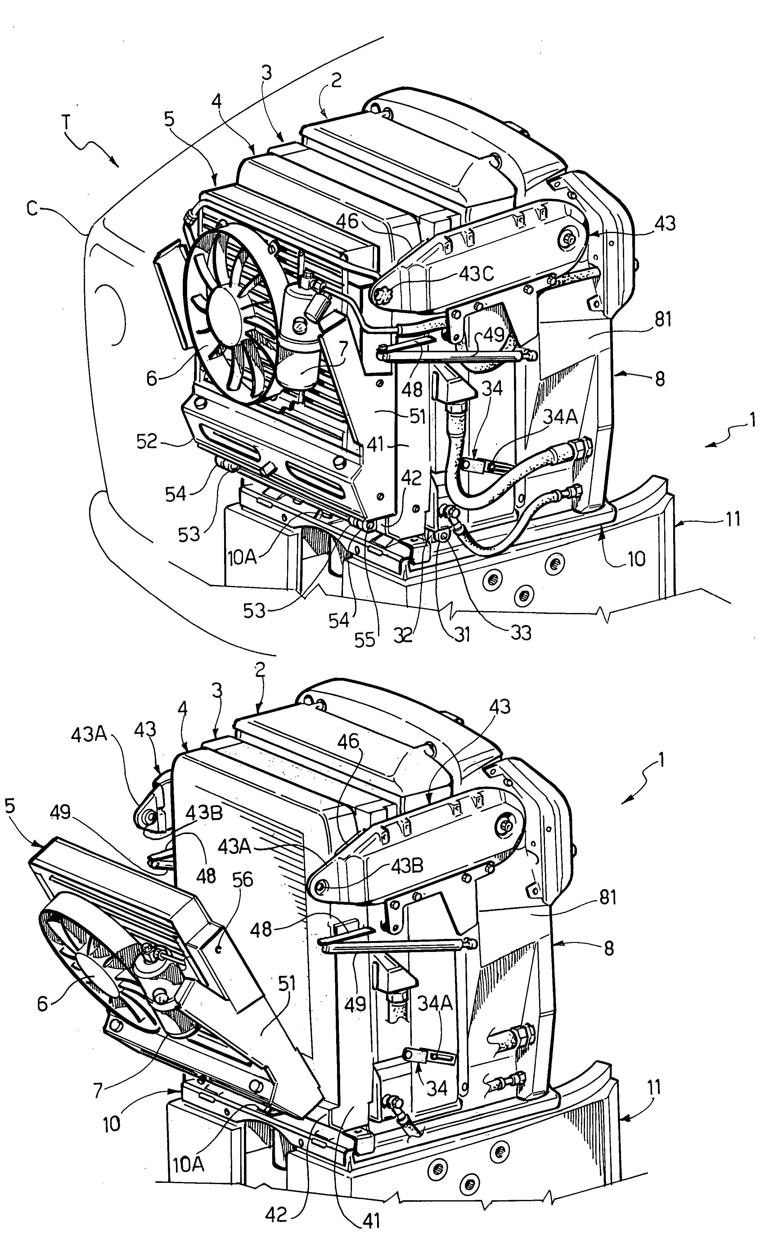
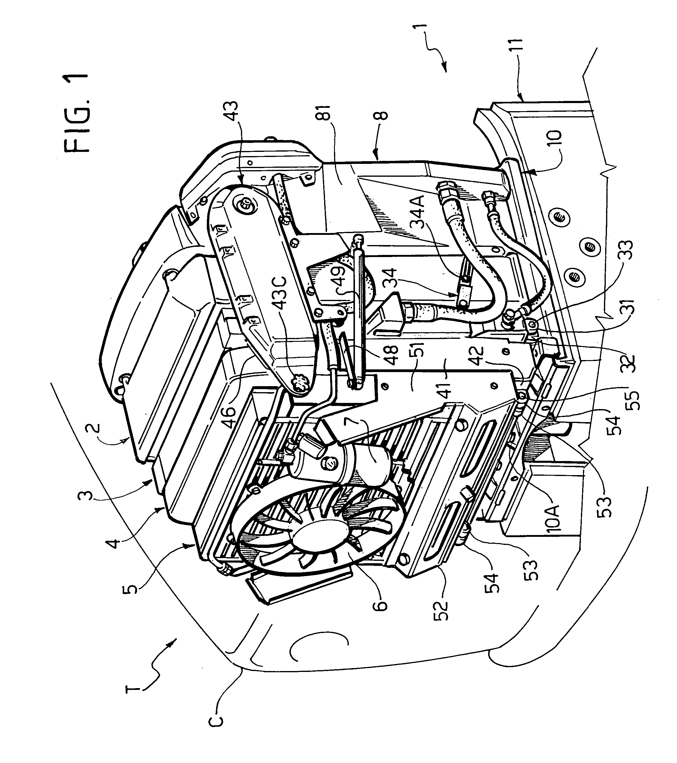
[0016]With reference to FIG. 1, T indicates the front portion of a farm tractor, comprising a bonnet C housing the internal combustion engine of the tractor, not shown. The present invention relates specifically to a farm tractor, but obviously it may also be applied to other types of farm machines, such as for instance combine-harvesters and the like.

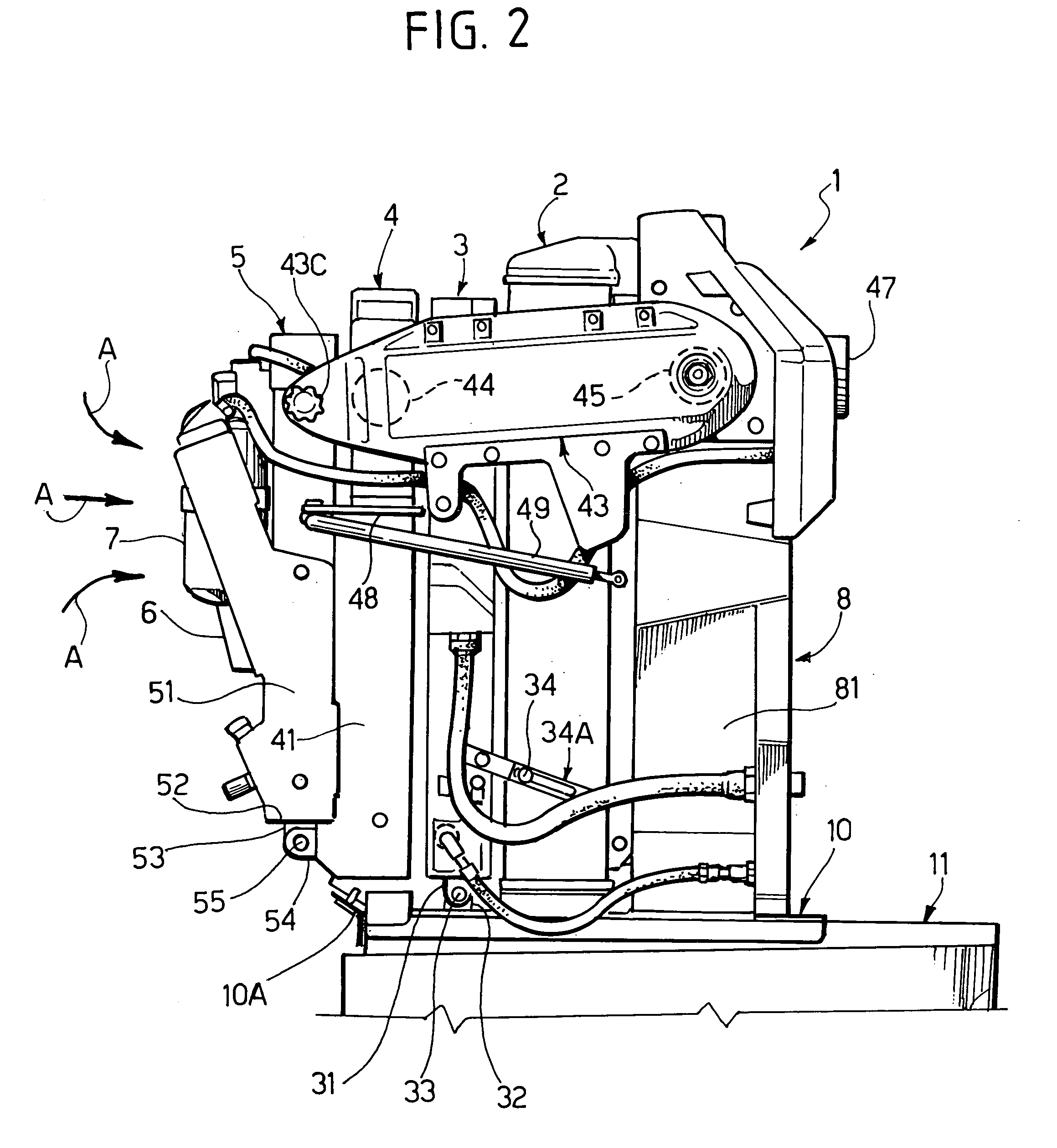
[0017]The hood C is provided with grille-like openings, not shown, for inlet and outlet of a cooling air flow. A heat exchange assembly, globally referred to with number 1, is housed in the front portion of the bonnet C. The heat exchange assembly 1 comprises an engine radiator 2, a gearshift oil radiator 3, a radiator 4 of an intercooler system, and a radiator 5 belonging to an air conditioning unit of the tractor cabin; the radiator 5 is associated in quite a conventional way with a respective fan 6 and a de-hydrating filter 7. As can be seen in particular in FIG. 2, the various radiators 2–5 of the assembly 1, globally prism-shaped,...


PUM


Abstract

A cooling system for a farm machine comprises a heat exchange assembly (1) having a plurality of radiators (2, 3, 4, 5) arranged one close to the other and so as to be passed through by a same air flow. According to the invention, at least a first radiator (3, 4, 5) can be shifted angularly with respect to a second radiator (2, 3, 4), so as to make cleaning operations for the latter easier.

Description

FIELD OF THE INVENTION[0001]The present invention refers to a cooling system for a farm machine.BACKGROUND OF THE INVENTION[0002]The engine of a farm machine is usually equipped with a cooling system comprising a heat exchange assembly including one or more radiators, typically a radiator for engine cooling, an intercooler and a radiator for gearshift oil cooling; in some cases the heat exchange assembly can also include a radiator belonging to an air conditioning unit of the farm machine cabin. Radiators are arranged so as to receive each a cooling air flow directed perpendicularly to their respective front surface.[0003]Traditionally, the heat exchange assembly is housed within a front bonnet of the machine, equipped with grille-like ventilation openings, provided on the side and / or on the front of said bonnet. Normally, said grille-like openings are designed to keep large-size impurities outside and enable an air filtration degree ensuring for most working activities in the field...

Claims


Application Information

Patent Timeline
Patent Type & Authority Patents(United States)
IPC IPC(8): B60H1/00B60K11/04F01P3/18F01P11/12F28D1/04F28F9/00
CPCB60K11/04F01P3/18F28F9/002F28D1/0435F01P11/12
Inventor ESPOSITO, GIOVANNIMARGUTTI, PIERANGELOBAUR, WOLFGANG
Owner SAME DEUTZ-FAHR
Why Eureka
Try Eureka