This helps you quickly interpret patents by identifying the three key elements:
Problems solved by technology
Method used
Benefits of technology
[0020]The third embodiment permits the invention to be adaptable to trigger spray bottles, much like my former patent U.S. Pat. No. 5,370,275 however, improvements have been made in the form of a pair of finger lift ledges and a pinch guard added to the outer surface of the outer housing. The pair of lift ledges protrude from the outer housing, thus allowing a single finger to support the entire container including the valve and trigger sprayer. This is a distinct advantage, as this addition permits valve use with symmetrically-shaped bottles which a
Problems solved by technology
This approach requires additional time to separately install the individual parts, thereby making robotic assembly techniques extremely difficult since the parts are small and must sequentially fit into the bore of
Method used
Image
Click on the blue label to locate the original text in one second.
Reading with bidirectional positioning of images and text.
Examples
third embodiment
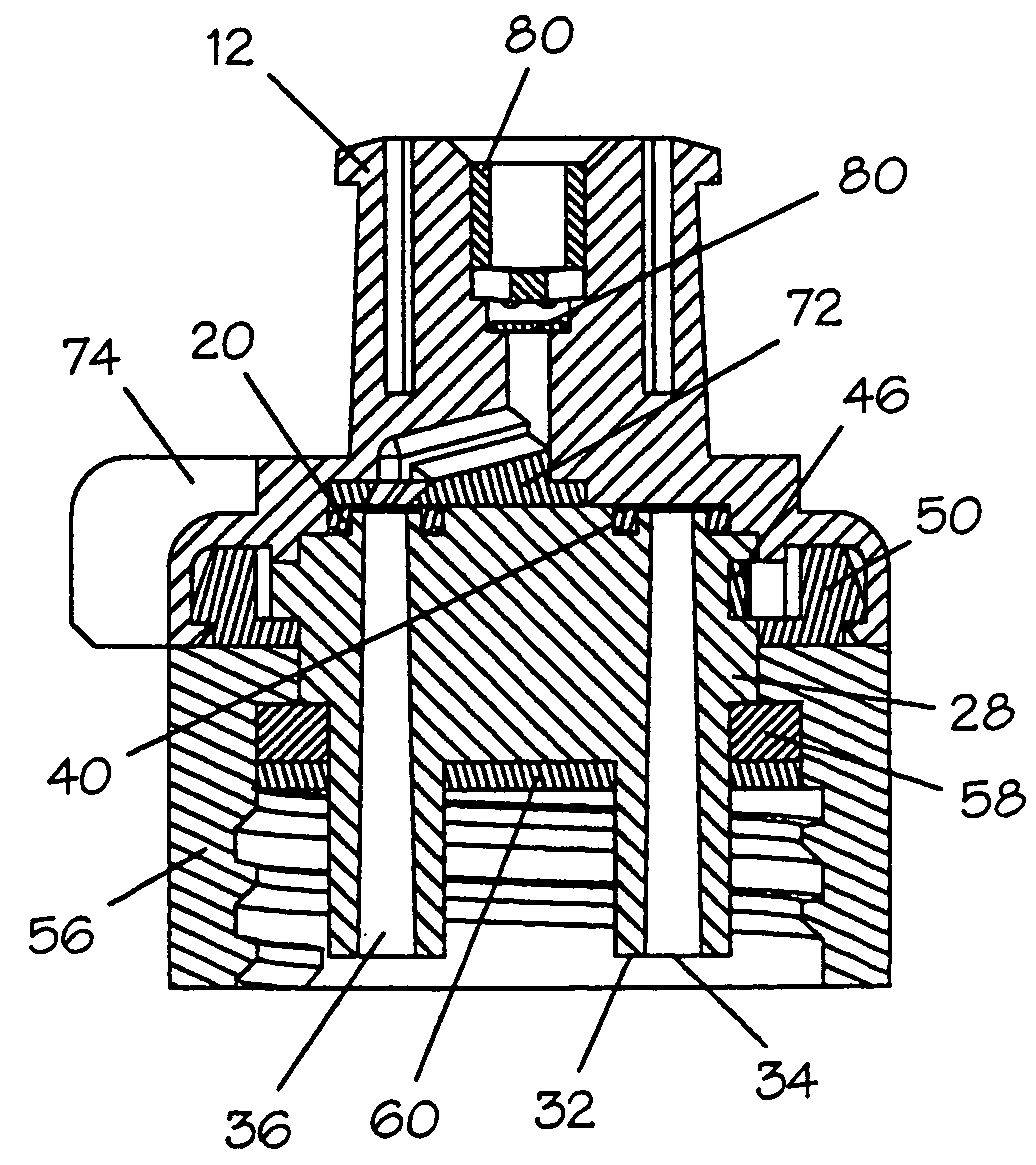
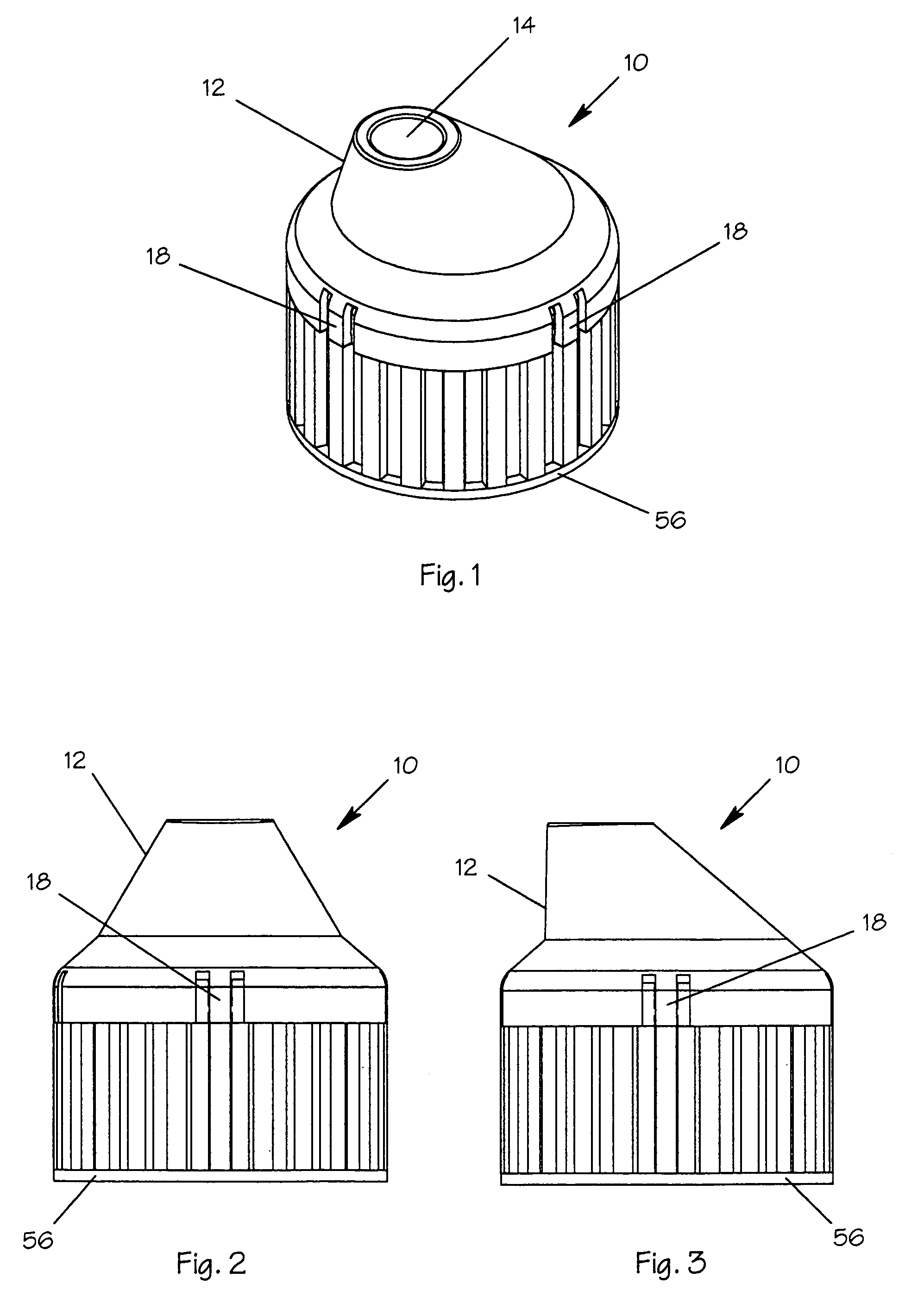
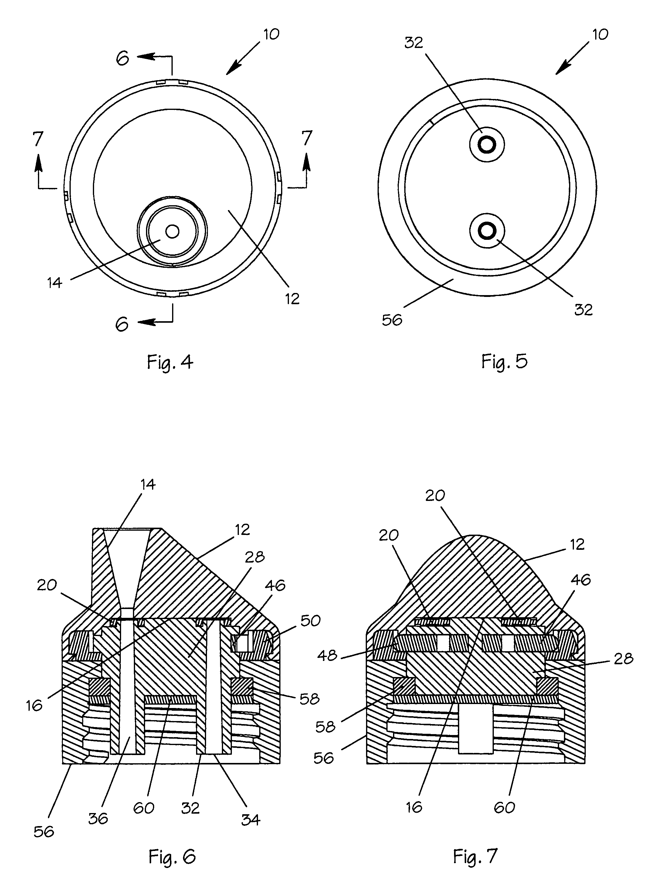
[0092]The best mode for carrying out the invention is presented in terms of a preferred, second and All three embodiments are basically the same in function and utilize the same components, with the exception of the outer housing which varies slightly in structure. The preferred embodiment, as shown in FIGS. 1–13 and 45–69, is comprised of a selection valve 10 that is used in conjunction with a multi-chambered fluid container, not shown, that has a plurality of container outlet openings in fluid communication with various container chambers for storing fluids. The container, which is sometimes referred to as a bottle, is well known in the art and is in common usage today, therefore it is deemed unnecessary to be illustrated in the drawings. The prior art multi-chambered container includes a pair of side-by-side isolated chambers. The liquids stored in the two chambers are not mixed until the liquids are poured from an opening on the top of the container. It should be noted that all...
second embodiment
[0101]The second embodiment, as illustrated in FIGS. 14–29 and FIGS. 45–69, is basically the same as the preferred embodiment with the exception of the outer housing, which instead of having a funnel shape is comprised of a cylindrical spout 62 having the offset bore 14 therethrougth and a stepped shoulder 64 with an outward-protruding offset bead 66 on a distal end.
[0102]A push pull closure 68 is slideably disposed on the cylindrical spout 62, and the closure 68 contains an offset bead 70 that corresponds to the outward-protruding offset bead 66 on the distal end of the spout 62. The offset bead 70 of the closure 68, being made of a resilient thermoplastic material, snaps over the offset bead 66 on the distal end of the spout 62. Upon assembly, the offset bead 66 acts as a stop for the offset bead 70 of the closure 68. The closure 68 plugs the bore 14 when urged downward on the spout 62, while a clear flow path is formed when pulled away from the spout end. The protruding bead 66 o...
PUM
Abstract
A selection valve (10) for use with a multi-chambered fluid container having outlet openings in communication with the fluid container chambers. The selection valve (10) utilizes an outer housing (12) having a bore (14) for receiving a fluid from the multi-chambered container. An upper gasket (20) engages an inner surface (16) of the outer housing (12) and an inner housing (28) having intake ports (34) that interface with the upper gasket, permitting communication between the outer housing (12) and the fluid container. A spring detent (46) is disposed upon the inner housing with protruding pins (48) that ride upon a rotating detent ring (50). When the housing (12) and the detent ring (50) rotate, the pins (48) enter radial grooves (54) and (55) causing the housing to remain at a desired location. A closure assembly is snapped onto the inner housing to permit a fluid path to be formed between a specific compartment in the container and the bore (14) in the outer housing.
Description
[0001]This application is a Divisional patent application of application Ser. No. 10 / 241,851, filing date Sep. 13, 2002 now U.S. Pat. No. 6,769,573.TECHNICAL FIELD[0002]The present invention pertains generally to valves for containers and more specifically to a valve that permits selection of one of a number of fluids from within a multi-chambered container utilizing a single dispensing method.BACKGROUND ART[0003]Previously, there have been many types of valves used to provide an effective means to pre-select a specific fluid from a multi-chambered container.[0004]A search of the prior art did not disclose any patents that possess the novelty of the instant invention, however the following U.S. patents are considered related:[0005]U.S. Pat. No.InventorIssue Date3,685,739VanierAug. 22, 19723,701,478TadaOct. 31, 19725,152,431Gardner, et al.Oct. 6, 19925,370,275Mills et al.Dec. 6, 19945,433,350GraubartJul. 18, 19955,685,351Kazarian, et al.Nov. 11, 1997[0006]U.S. Pat. No. 3,685,739 disc...
Claims
Application Information
Patent Timeline
Application Date:The date an application was filed.
Publication Date:The date a patent or application was officially published.
First Publication Date:The earliest publication date of a patent with the same application number.
Issue Date:Publication date of the patent grant document.
PCT Entry Date:The Entry date of PCT National Phase.
Estimated Expiry Date:The statutory expiry date of a patent right according to the Patent Law, and it is the longest term of protection that the patent right can achieve without the termination of the patent right due to other reasons(Term extension factor has been taken into account ).
Invalid Date:Actual expiry date is based on effective date or publication date of legal transaction data of invalid patent.