Hand-held setting tool

a technology of setting tool and hand, which is applied in the direction of manufacturing tools, stapling tools, nailing tools, etc., can solve the problems of inadvertent displacement of pressure probes and inadvertent actuation of setting tools, and achieves simple gravity force control, simple blockage means, and easy production

Active Publication Date: 2006-08-15
HILTI AG
View PDF9 Cites 11 Cited by
  • Summary
  • Abstract
  • Description
  • Claims
  • Application Information

AI Technical Summary

Benefits of technology

[0009]As a result of the present invention, there is provided tool position-dependent blocking means for the pressure probe and which prevents displacement of the pressure probe into its operational position at least in a vertical position of the setting tool when the front part of the tool is spaced from a constructional component. Thereby, an inadvertent actuation of a setting tool during its disassembly is prevented. The blocking means are very simple and can be easily produced.
[0010]Advantageously, the blocking means includes a blocking member guide opening in a direction of the pressure probe guide and extending relative thereto, in the setting direction, at an angle smaller than 90°. The angular arrangement of the blocking member guide provides for a simple gravity force control. Because the blocking member guide does not extend to the pressure probe guide at a right angle, in the disassembly position of the setting tool (with the outlet opening part being spaced from a constructional component in a direction of the gravity force), the blocking member will be displaced into the pressure probe guide along an inclination surface of the blocking member guide.
[0011]Advantageously, the blocking member is formed as a ball, whereby a more rapid reaction time of the blocking means is attained. This is because a ball can be displaced along the inclination of the blocking member guide very rapidly under the action of the gravity force.
[0012]Advantageously, the pressure probe guide has a guide channel the diameter of which is smaller than the diameter of the blocking member, in particular when the blocking member is formed as a ball. This prevents displacement of the blocking member in the pressure probe guide.

Problems solved by technology

However, the drawback of the known setting tool consists in that an inadvertent displacement of the pressure probe can take place when the setting tool is placed, for disassembly purposes, with its back on a constructional component with the outlet opening facing upward.
This can lead to the danger of an inadvertent actuation of the setting tool.

Method used


Image

  • Hand-held setting tool
  • Hand-held setting tool
  • Hand-held setting tool

Examples


Embodiment Construction

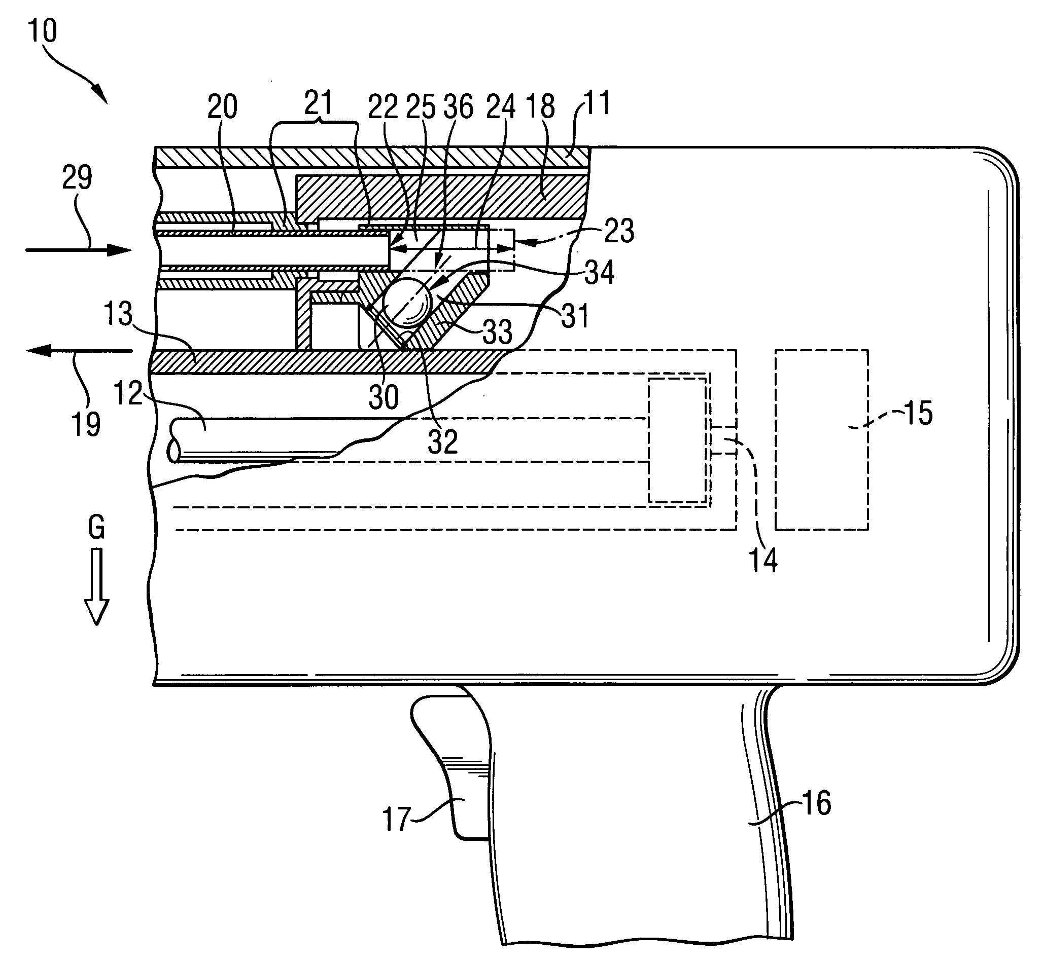
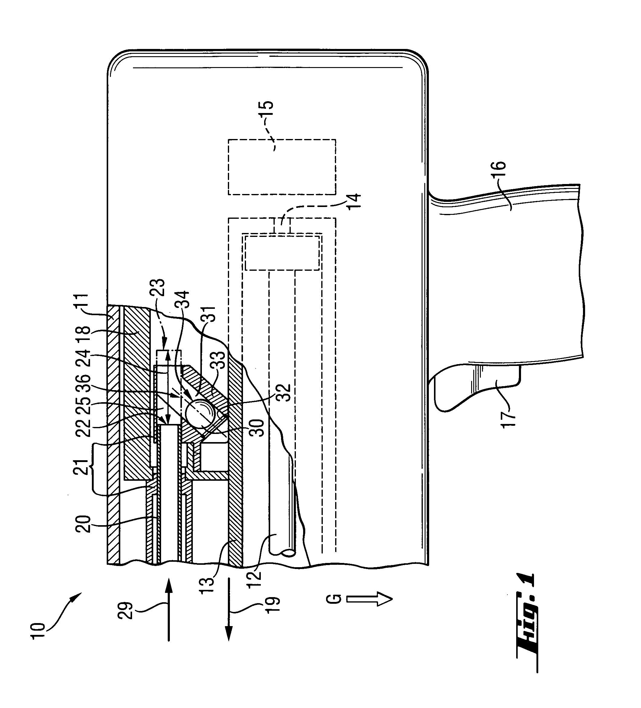
[0017]FIG. 1 shows a rear portion of a combustion-operated, hand-held setting tool 10 and which is spaced from the outlet opening of the setting tool 10. The setting tool 10 has a one-or multi-part housing 11 in which a setting mechanism is arranged. The setting mechanism includes a piston guide 13 in which a drive piston 12 is displaceable for driving fastening elements in objects such as constructional components. At the end of the piston guide 13 facing in the direction opposite a setting direction 19, there is arranged a propellant socket 14 such as a cartridge socket in which a propellant is fed. For an electronic, mechanical, or electrical ignition of a propellant located in the propellant socket 14, there is provided an ignition unit 15. For actuation of a setting process, an actuation switch 17 is provied on a handle 16 of the setting tool 10.

[0018]The setting tool 10 also includes a front part with the outlet opening (not shown) and facing in the setting direction 19. The f...


PUM

PropertyMeasurementUnit
angleaaaaaaaaaa
gravity forceaaaaaaaaaa
diameteraaaaaaaaaa

Abstract

A hand-held setting tool for driving in fastening elements includes a pressure probe (20) displaceable between an extended position (22) in which the setting tool (10) cannot be actuated, and an operational position (23) in which the setting tool (10) can be actuated, and a blocking member (30) displaceable by a gravity force between its release position (34) in which it is located outside of a displacement path (24) of the pressure probe (20), and a blocking position (35) in which it extends into the displacement path (24) of the pressure probe (20), blocking displacement of a pressure probe (20) into its operational position.

Description

BACKGROUND OF THE INVENTION[0001]1. Field of the Invention[0002]The present invention relates to a setting tool for driving in fastening elements and including a guide, a pressure probe displaceable between its extended position in, which the setting tool cannot be actuated, and its operational position in which the setting tool can be actuated.[0003]2. Description of the Prior Art[0004]Hand-held setting tools of the type described above can be operated with solid, gaseous, or liquid fuels or with compressed air. In the combustion-operated setting tools, the setting piston is driven by high-pressure combustion gases of a propellant. The setting piston drives fastening elements in constructional components.[0005]For safety reason, usually, setting tools, which work with high-pressure gases, are equipped with means for sensing a press-on condition of a setting tool. The sensing means includes at least one pressure probe that projects beyond the front part of the setting tool and in wh...

Claims


Application Information

Patent Timeline
Patent Type & Authority Patents(United States)
IPC IPC(8): B21J15/28B25C1/00B25C1/14
CPCB25C1/14B25C1/008
Inventor BUECHEL, JOHANNJAKOB, ROBERTSCHALBETTER, DIONYS
Owner HILTI AG
Why Eureka
Try Eureka