Preconnectorized fiber optic drop cables and assemblies for efficient deployment

a technology of fiber optic drop cables and fiber optic assemblies, applied in the field of optical networks, can solve the problems of -haul links having bandwidth capacity, copper cables have drawbacks, and transmit relatively limited amounts of data

Inactive Publication Date: 2006-08-15
CORNING OPTICAL COMM LLC
View PDF37 Cites 368 Cited by
  • Summary
  • Abstract
  • Description
  • Claims
  • Application Information

AI Technical Summary

Problems solved by technology

However, copper cables have drawbacks because they are large, heavy, and can only transmit a relatively limited amount of data.
However, many of these long-haul links have bandwidth capacity that is not being used.
In other words, subscribers have a limited amount of available bandwidth due to the constraints of copper cables in the communication network.
But there are certain obstacles that make it challenging and / or expensive to route optical waveguides / optical cables deeper into the communication network, i.e., closer to the subscriber.
For instance, making a suitable optical connection between optical waveguides is much more difficult than making an electrical connection between copper wires.
Additionally, as the communication network pushes toward subscribers, the communication network requires more connections, which compounds the difficulties of providing optical waveguides to the premises of the subscriber.
Hence, the routing of optical waveguides to the proverbial last mile of the network has yet to enjoy commercial success.
Polishing a ferrule is a relatively complex process that generally requires several steps along with inspection and testing using precision equipment to verify an acceptable insertion loss.
But like connectors, fusion splicing requires highly trained craftsman and special equipment to make and test the optical connection, thereby making it a relatively expensive and inefficient proposition for field connectorization.

Method used


Image

  • Preconnectorized fiber optic drop cables and assemblies for efficient deployment
  • Preconnectorized fiber optic drop cables and assemblies for efficient deployment
  • Preconnectorized fiber optic drop cables and assemblies for efficient deployment

Examples


Embodiment Construction

[0027]The present invention will now be described more fully hereinafter with reference to the accompanying drawings showing preferred embodiments of the invention. The invention may, however, be embodied in many different forms and should not be construed as limited to the embodiments set forth herein; rather, these embodiments are provided so that the disclosure will fully convey the scope of the invention to those skilled in the art. The drawing are not necessarily drawn to scale but are configured to clearly illustrate the invention.

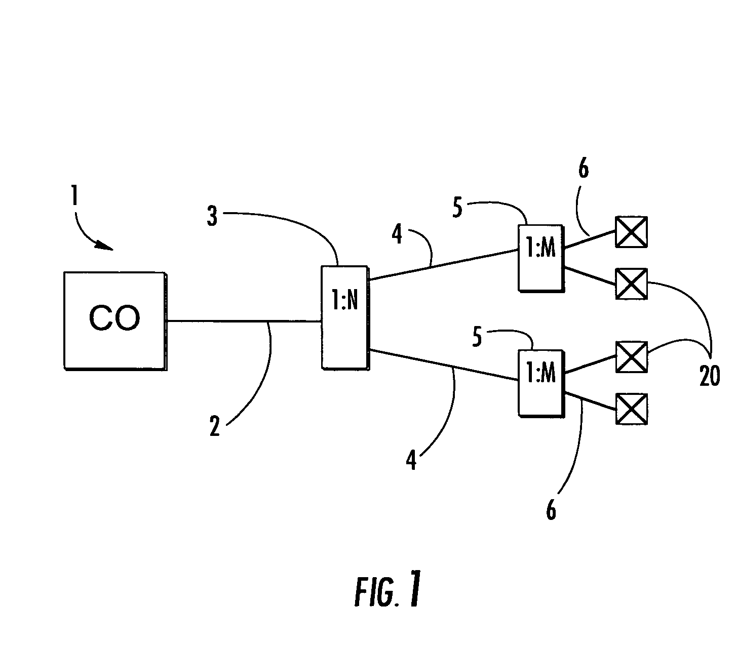
[0028]FIG. 1 schematically depicts a portion of an optical waveguide network 1 in an exemplary fiber to the location ‘x’ (FTTx). ‘x’ in the acronym represents the end location of the optical waveguide, for instance, FTTC is fiber to the curb. In this case, network 1 is a fiber to the premises (FTTP) application. FTTP architectures advantageously route at least one optical waveguide to the premises, thereby providing a high bandwidth connection to the...


PUM


Abstract

A preconnectorized outdoor cable streamlines the deployment of optical waveguides into the last mile of a optical network. The preconnectorized outdoor cable includes a cable and at least one plug connector. The plug connector is attached to a first end of the cable, thereby connectorizing at least one optical waveguide. The cable has at least one optical waveguide, at least one tensile element, and a cable jacket. Various cable designs such as figure-eight or flat cables may be used with the plug connector. In preferred embodiments, the plug connector includes a crimp assembly having a crimp housing and a crimp band. The crimp housing has two half-shells being held together by the crimp band for securing the at least one tensile element. When fully assembled, the crimp housing fits into a shroud of the preconnectorized cable. The shroud aides in mating the preconnectorized cable with a complimentary receptacle.

Description

RELATED APPLICATIONS[0001]The present application is a Continuation-in-Part of U.S. Ser. No. 10 / 659,666 filed on Sep. 10, 2003 now U.S. Pat. No. 6,899,467, which is a Divisional of U.S. Ser. No. 09 / 967,259 filed on Sep. 28, 2001 now U.S. Pat. No. 6,648,520. The present application is also a Continuation-in-Part of U.S. Ser. No. 10 / 294,136 filed on Nov. 14, 2002 now U.S. Pat. No. 6,714,710, which is a Continuation of U.S. Ser. No. 09 / 645,916 filed on Aug. 25, 2000 now U.S. Pat. No. 6,542,674. The present application is also a Continuation-in-Part of U.S. Ser. No. 10 / 383,468 filed on Mar. 7, 2003 now U.S. Pat. No. 6,785,450, which is a Continuation of U.S. Ser. No. 09 / 579,555 filed on May 26, 2000 now U.S. Pat. No. 6,546,175. The present application is also related to U.S. patent application Ser. No. 10 / 765,262 titled “Figure-Eight Preconnectorized Fiber Optic Drop Cables and Assemblies” and Ser. No. 10 / 765,434 titled “Preconnectorized Fiber Optic Drop Cables and Assemblies” filed on ...

Claims


Application Information

Patent Timeline
Patent Type & Authority Patents(United States)
IPC IPC(8): G02B6/00G02B6/38G02B6/44
CPCG02B6/3869G02B6/387G02B6/3894G02B6/3897G02B6/4405G02B6/4429G02B6/4433G02B6/3849G02B6/3821G02B6/4494G02B6/3851G02B6/3879G02B6/3885G02B6/3887G02B6/4416G02B6/4465G02B6/3889G02B6/3888G02B6/545G02B6/44384
Inventor MELTON, STUART R.TRAN, HIEU V.THOMPSON, DAVID A.WAGMAN, RICHARD S.GIMBLET, MICHAEL J.LIU, XIN
Owner CORNING OPTICAL COMM LLC
Why Eureka
Try Eureka