
Twist lock panel-mounted connector

a technology of twist lock and connector, which is applied in the direction of electrical equipment, substation/switching arrangement details, coupling device connections, etc., to achieve the effect of simple mounting aperture shape, less manufacturing precision, and easy resilient deflectability

Active Publication Date: 2006-08-15
SUMITOMO WIRING SYST LTD
View PDF11 Cites 37 Cited by
  • Summary
  • Abstract
  • Description
  • Claims
  • Application Information

AI Technical Summary

Benefits of technology

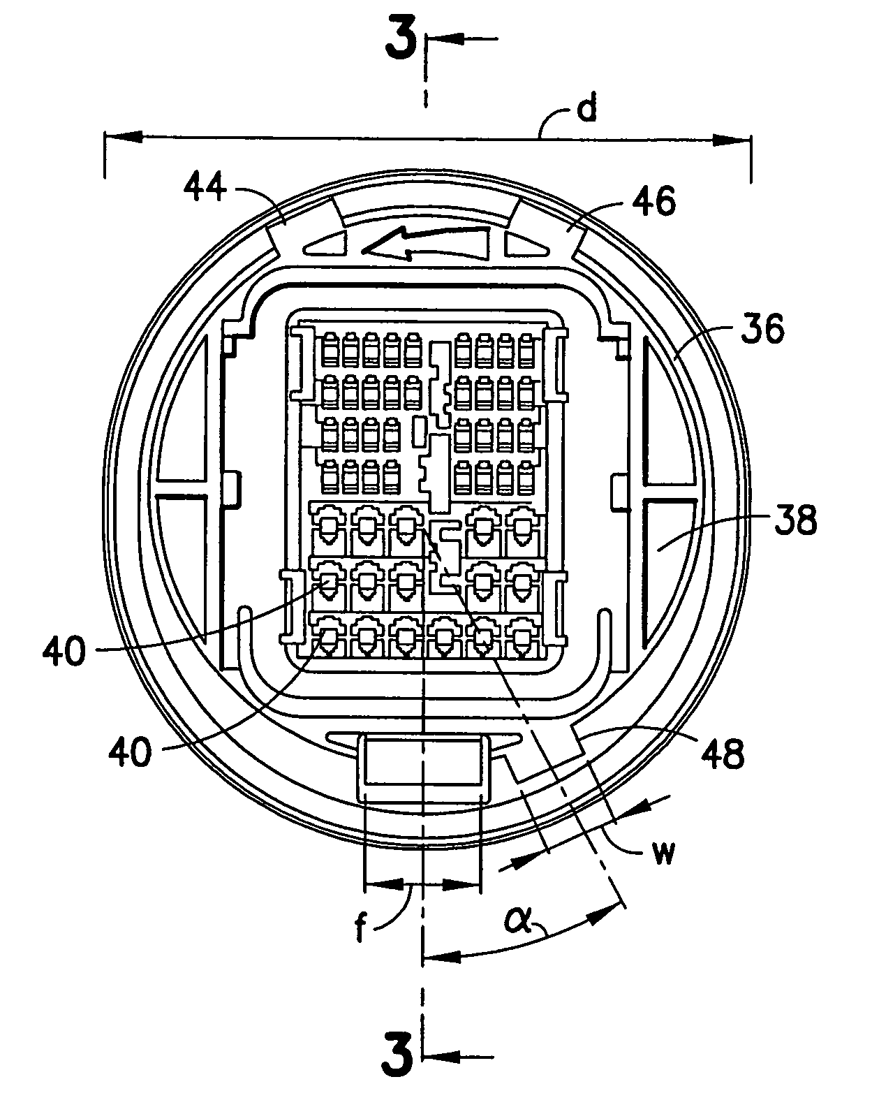
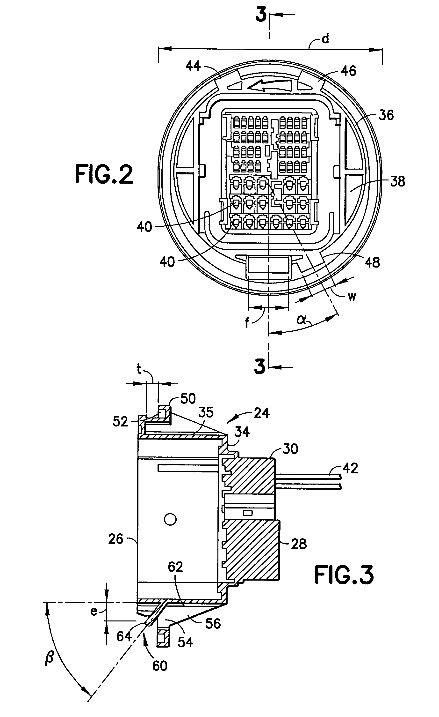
[0017]The housing is mounted to the panel by aligning the key with the keyway and inserting the front end of the housing through the mounting aperture of the panel. This is insertion will cause the leading end of the resiliently deflectable locking finger to engage the rear surface of the panel at locations adjacent the mounting aperture. As a result, the locking finger will deflect resiliently and will exert a resilient biasing force against the rear surface of the panel. The stop flange contacts the rear surface of the panel to limit the amount of insertion of the housing through the mounting aperture. At this position, the key will still be aligned with the keyway, but will be slightly forward of the front surface of the panel. The housing then is rotated relative to the panel. The key will still be forward of the panel, but will no longer align with the keyway. Therefore, the panel will be sandwiched between the key and the stop flange. Sufficient rotation of the housing will cause the locking finger to align with the keyway. As a result, the locking finger will return resiliently to an undeflected position in the keyway. The positioning of the locking finger in the keyway will prevent any further rotation of the housing relative to the panel.
[0018]The locking finger preferably is dimensioned to avoid projecting significantly forward of the panel. Thus, the locking finger is not likely to be contacted inadvertently from the front of the panel, and locked retention of the housing on the panel is more secure.
[0019]Support walls may project rearward from stop flange to the outer surface of the housing to support the stop flange. The support walls may also be near the locking finger to prevent inadvertent contact with the locking finger at locations rearward of the panel. Thus, locked retention of the housing on the panel is even more secure.
[0021]The mounting aperture in the panel does not require a separate rotation limiting slot or opening. Therefore, the shape of the mounting aperture is simple and requires less manufacturing precision than designs that require both locating slots and rotation limiting slots.
[0022]The locking finger preferably is configured to be easily resiliently deflectable about one axis, but is substantially undeflectable about other axes. The axis of deflection preferably is substantially normal to the mounting direction of the housing on the panel. Thus, the locking finger will deflect easily as the housing is being mounted on the panel. However, the locking finger will provide good resistance to rotation after the locking finger is in the key way.

Problems solved by technology

Sufficient rotation of the housing will cause the locking finger to align with the keyway.

Method used


Image

  • Twist lock panel-mounted connector
  • Twist lock panel-mounted connector
  • Twist lock panel-mounted connector

Examples


Embodiment Construction

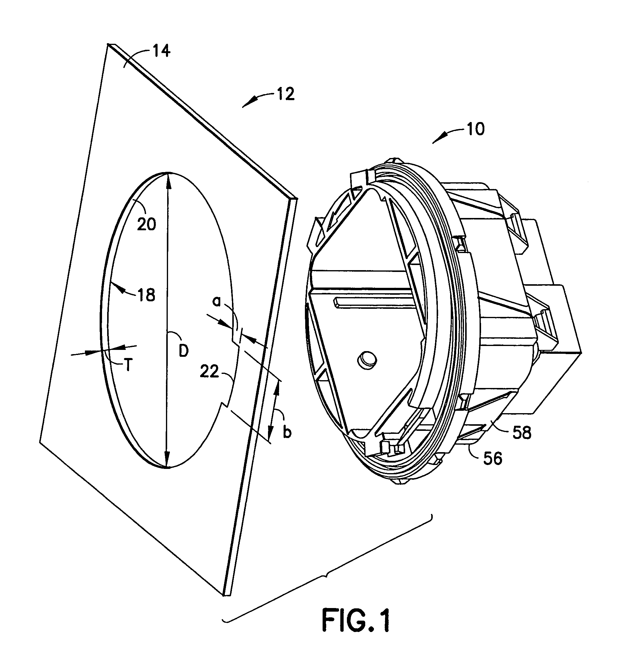
[0032]A connector according to the invention is identified generally by the numeral 10 in FIGS. 1 to 9. The connector 10 is mountable to a panel 12, such as the metal panel of a vehicle door. Thus, the connector 10 enables electrical connections to be made between a vehicle body and a vehicle door. The panel 12 has opposite front and rear surfaces 14 and 16 defining a thickness T. A mounting aperture 18 extends through the panel 12 from the front surface 14 to the rear surface 16. The mounting aperture 18 has a substantially circularly generated edge 20 with a diameter D, and a generally rectangular keyway 22 extends out from the circularly generated edge 20. The keyway 22 has a radial dimension “a” of about 0.25 inch and tangential or width dimension “b” of about 0.50 inch. In the illustrated embodiment, the keyway 22 extends through an arc of between about 10° and 20°.

[0033]The connector 10 has a housing 24 that is formed unitarily from a synthetic resin. The housing 24 has a fron...


PUM


Abstract

A connector (10) is configured for mounting to a panel (12). The panel (12) has a mounting aperture (18) formed with a keyway (22). The connector (10) has a housing (24) with a front end (26) dimensioned to pass through the mounting aperture (18). However, keys (44, 46, 48) project out in proximity to the front end (26) of the housing (24). At least one of the keys (48) is dimensioned to pass through the keyway (22). A stop flange (50) projects out from the housing (24) rearward of the keys (44, 46, 48). A resiliently deflectable locking finger (60) projects forward of the stop flange (50) and is dimensioned to engage in the keyway (22).

Description

BACKGROUND OF THE INVENTION[0001]1. Field of the Invention[0002]The invention relates to a panel mounted connector.[0003]2. Description of the Related Art[0004]A panel mounted connector includes a housing with opposite front and rear ends and a plurality of cavities extending between the ends. Terminal fittings are connected to ends of wires and are mounted in the respective cavities in a rear-to-front direction so that the wires extend from the rear end of the housing. Locks are formed in the cavities and / or on the terminal fittings so that the terminal fittings are locked in specified positions within the respective cavities.[0005]The housing of the panel mounted connector is configured to be mounted to a panel, such as a panel in an automotive vehicle or an apparatus. The panel has opposite front and rear surfaces, and a mounting aperture extends through the panel from the front surface to the rear surface. The mounting aperture is configured to receive the front end of the housi...

Claims


Application Information

Patent Timeline
IPC IPC(8): H01R13/73
CPCH01R13/743H01R13/645
Inventor HOUCK, DAVIDNEVILLE, EMILYMAUNEY, JOSEPH
Owner SUMITOMO WIRING SYST LTD
Learn More