Belt sander

a belt sander and belt technology, applied in the field of belt sanders, can solve the problems of decreasing the working efficiency decreasing the etc., and achieve the effect of smooth grinding of wooden materials, enhancing the grinding and finishing effect of the belt sander, and increasing the grinding path and area of the sand bel

Active Publication Date: 2006-08-15
WANG TIAN WANG
View PDF2 Cites 16 Cited by
  • Summary
  • Abstract
  • Description
  • Claims
  • Application Information

AI Technical Summary

Benefits of technology

[0010]A further objective of the present invention is to provide a belt sander, wherein the grinding path and area of the sand belt are increased largely by the reciprocally and successively swinging action of the swinging device and the sanding device, so that the sand belt can be used to grind the wooden material exactly and efficiently, thereby greatly enhancing the grinding and finishing effect of the belt sander.
[0011]A further objective of the present invention is to provide a belt sander, wherein the sand belt can be used to grind the wooden material smoothly, thereby preventing the wooden material from being scratched or worn by the sand belt so as to enhance the quality of the wooden material.
[0012]A further objective of the present invention is to provide a belt sander, wherein the wooden chips produced during the grinding process are not easily attached to the surface of the sand belt by the reciprocally and successively swinging action of the swinging device and the sanding device, so that the wooden chips can be cleaned easily and conveniently, thereby enhancing the working efficiency of the belt sander.

Problems solved by technology

However, the sand belt of the belt sander has a surface formed with particles arranged in an irregular manner, so that the surface of the wooden material is easily scratched by the sand belt, thereby decreasing the finishing effect of the belt sander.
Thus, the worker has to clear the surface of the sand belt frequently, thereby decreasing the working efficiency of the belt sander.

Method used


Image

  • Belt sander
  • Belt sander
  • Belt sander

Examples


Embodiment Construction

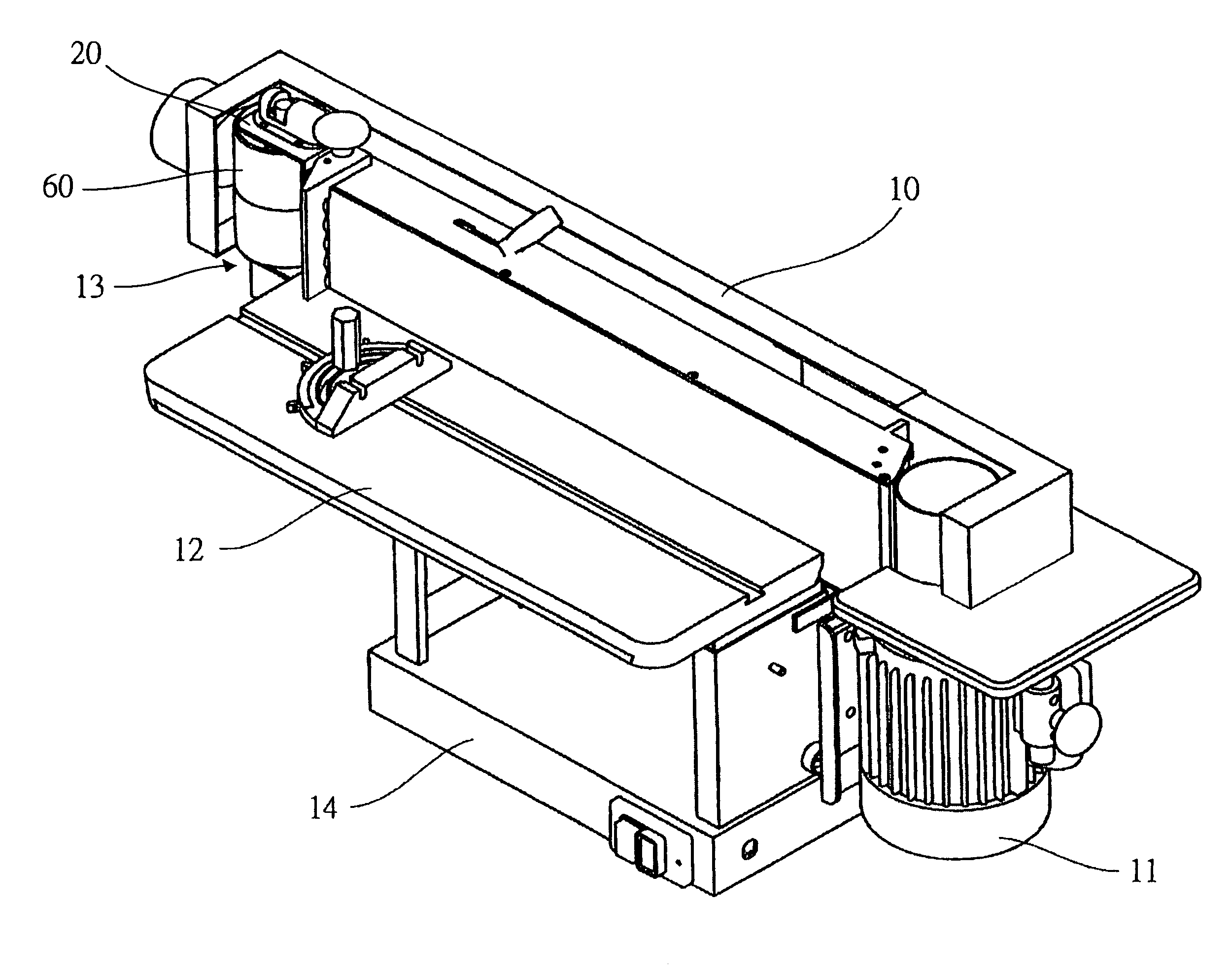
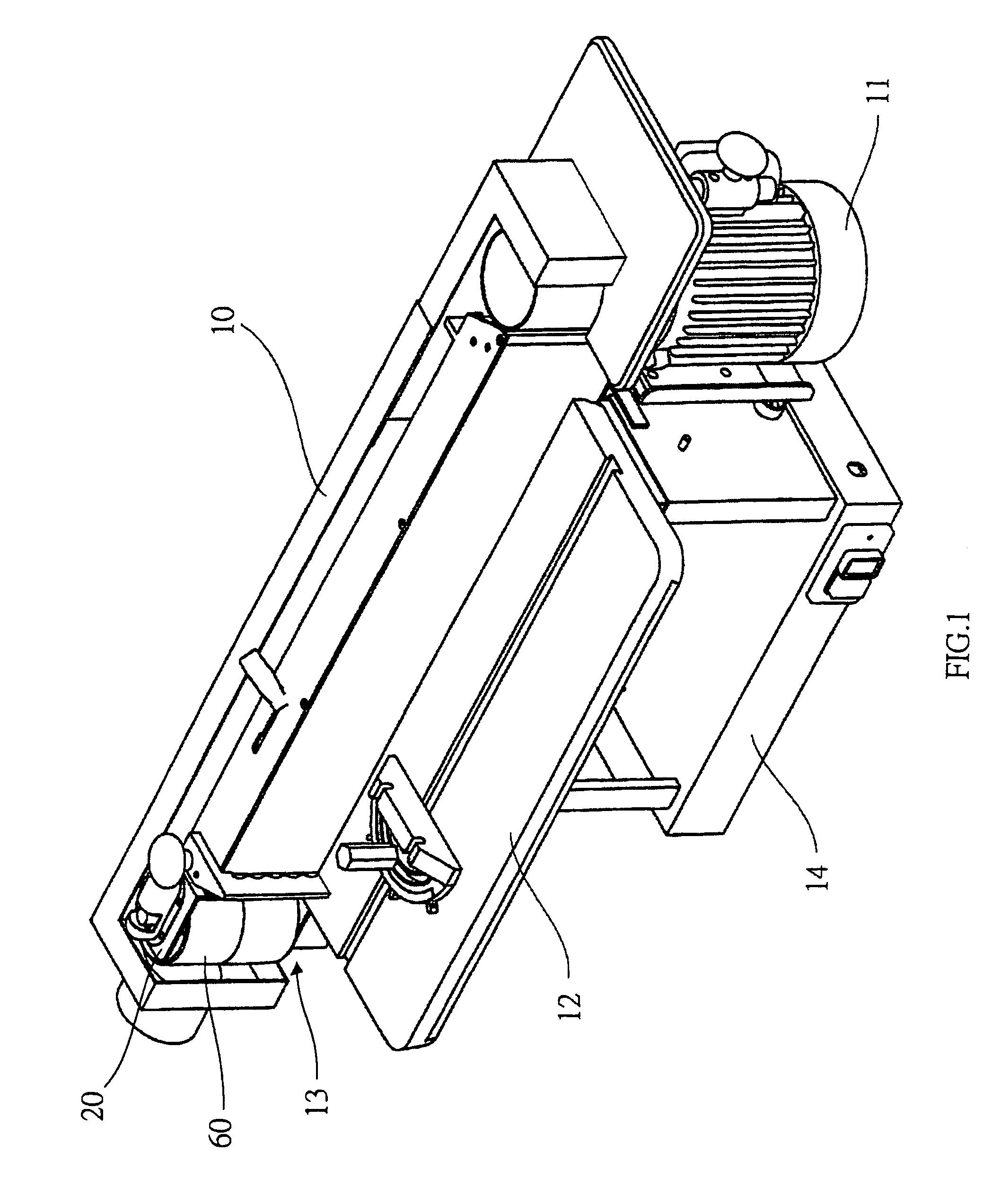
[0019]Referring to the drawings and initially to FIGS. 1–3, a belt sander in accordance with the preferred embodiment of the present invention comprises a base 14, a sanding device 10 mounted on an upper portion of the base 14, a worktable 12 mounted on a front portion of the sanding device 10, a tipping drive device 11 mounted on a first side of the sanding device 10 to adjust the angle of the sanding device 10 so as to satisfy different working requirements, and a swinging device 13 mounted on a second side of the sanding device 10.

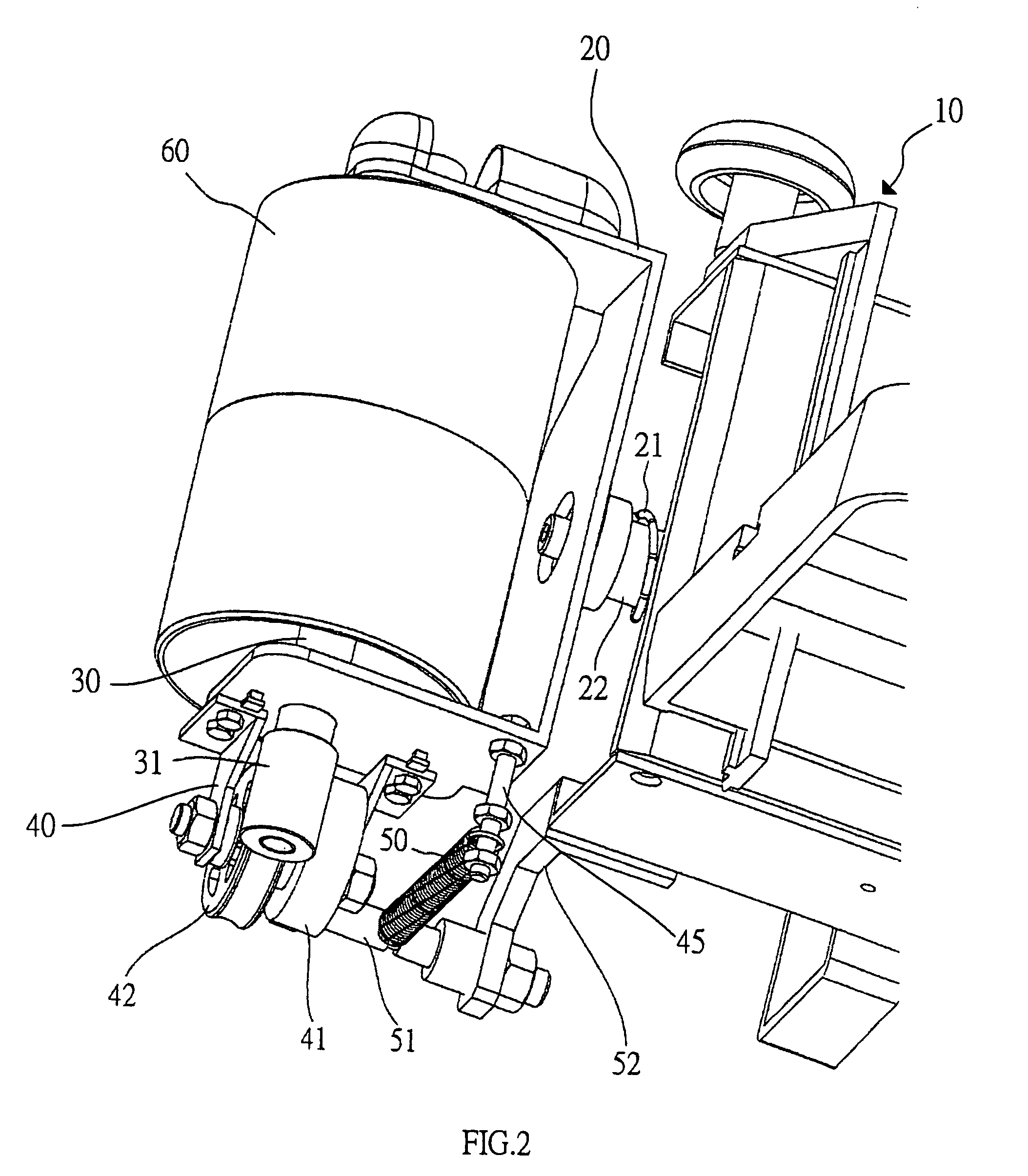
[0020]The swinging device 13 includes a cylindrical roller 60 rotatably mounted on the second side of the sanding device 10 and rotated by the sanding device 10, a central shaft 30 mounted in the roller 60 to rotate therewith, a toothed ring 31 mounted on a lower end of the central shaft 30 to rotate therewith, a drive gear 42 meshing with and rotated by the toothed ring 31, a cam 41 mounted on and rotated by the drive gear 42, a fixing rod 51 mounted o...


PUM


Abstract

A belt sander includes a base, a sanding device, a worktable, a tipping drive device, and a swinging device. The swinging device includes a cylindrical roller, a central shaft, a toothed ring, a drive gear, a cam, and a fixing rod. The swinging device drives the sanding device to produce a slightly reciprocally swinging action during operation of the sanding device. Thus, the grinding path and area of the sand belt are increased largely by the reciprocally and successively swinging action of the swinging device and the sanding device, so that the sand belt can be used to grind the wooden material exactly and efficiently, thereby greatly enhancing the grinding and finishing effect of the belt sander.

Description

BACKGROUND OF THE INVENTION[0001]1. Field of the Invention[0002]The present invention relates to a belt sander, and more particularly to a belt sander having a reciprocally swinging effect.[0003]2. Description of the Related Art[0004]A belt sander is used to grind and finish a wooden material. However, the sand belt of the belt sander has a surface formed with particles arranged in an irregular manner, so that the surface of the wooden material is easily scratched by the sand belt, thereby decreasing the finishing effect of the belt sander. In addition, the sand belt of the belt sander has a rough surface, so that the wooden chips produced during the grinding process are easily attached to the surface of the sand belt. Thus, the worker has to clear the surface of the sand belt frequently, thereby decreasing the working efficiency of the belt sander.[0005]A conventional belt sander in accordance with the prior art was disclosed in his U.S. Pat. No. 6,283,841-B1.SUMMARY OF THE INVENTI...

Claims


Application Information

Patent Timeline
Patent Type & Authority Patents(United States)
IPC IPC(8): B24B21/00
CPCB24B21/22
Inventor WANG, TIAN-WANG
Owner WANG TIAN WANG
Why Eureka
Try Eureka