Frequency generator and communication system
a frequency generator and communication system technology, applied in the field of frequency generators, can solve problems such as circuit operation and value not being a desired value for oscillation frequency
- Summary
- Abstract
- Description
- Claims
- Application Information
AI Technical Summary
Benefits of technology
Problems solved by technology
Method used
Image

Examples
first embodiment
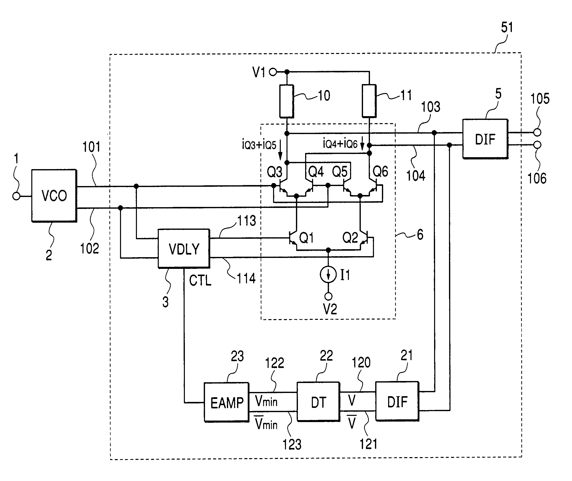
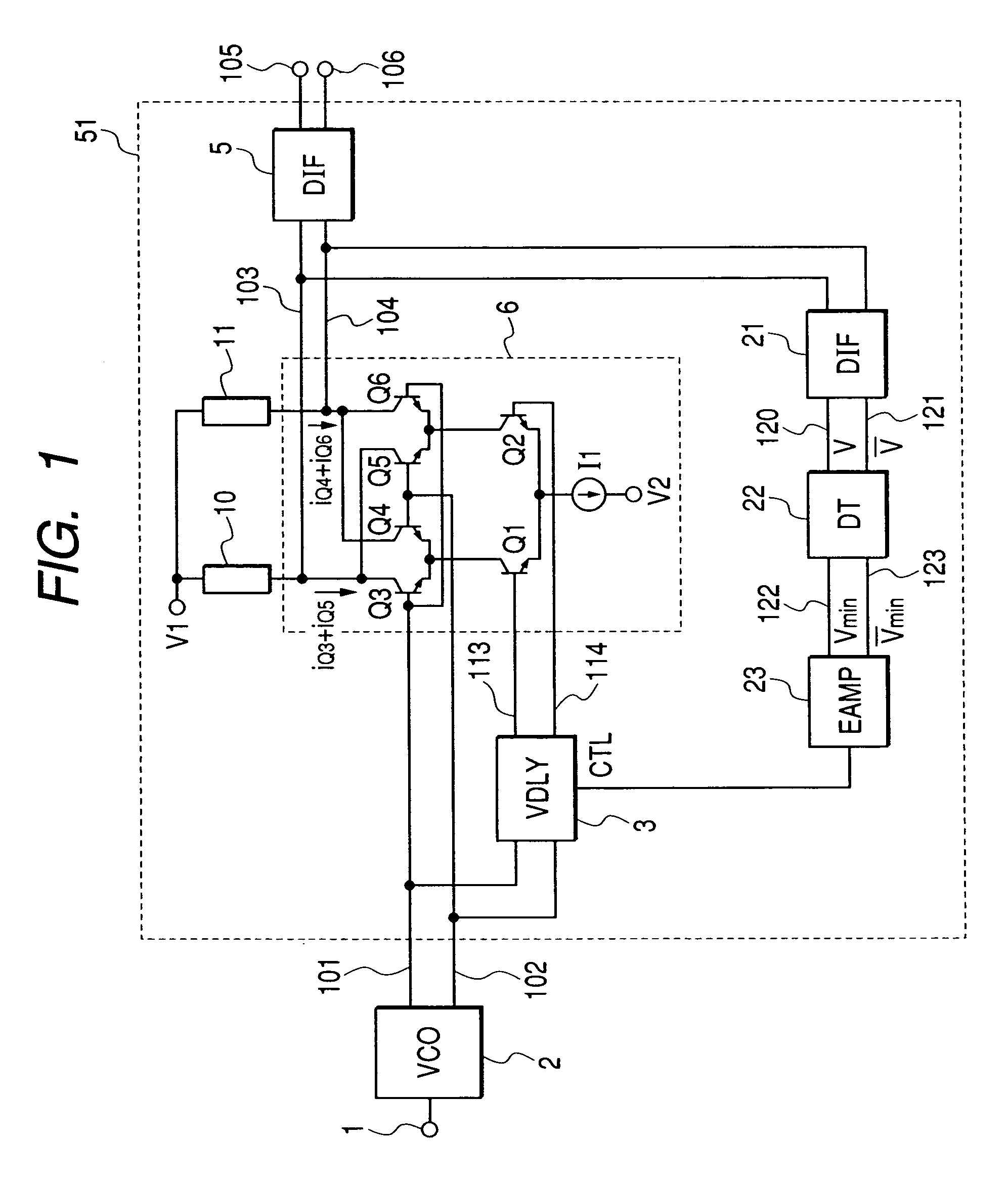
[0061]FIG. 1 is a circuit diagram showing a first embodiment of the frequency generator according to the invention. A frequency doubler 51 in this embodiment is composed of a variable delay circuit (VDLY) 3, differential amplifiers (DIF) 5, 21, a Gilbert-type multiplier 6 which is a first configurational example, load circuits 10, 11, a voltage-swing detection circuit (DT) 22 and an error amplifier (EAMP) 23.
[0062]As in the first conventional type example, in a voltage controlled oscillator (VCO) 2, the oscillation frequencies of differential output signals 101 and 102 are controlled by voltage applied to a frequency control terminal 1. The Gilbert-type multiplier 6 is composed of differential pairs Q1 and Q2, Q3 and Q4, Q5 and Q6 of bipolar transistors. Output currents iQ3+iQ5, iQ4+iQ6 proportional to the result of the multiplication of two differential input voltage are sunk from a common collector of the transistors Q3 and Q5 and from a common collector of the transistors Q4 and ...
second embodiment
[0078]FIG. 5 is a circuit diagram showing a second embodiment of the frequency generator according to the invention. To avoid the repetition of the description, the same reference number is allocated to the same component as that in the first embodiment and the detailed description is omitted. This embodiment is different from the first embodiment in a feedback path forming a path from output nodes 103, 104 of a Gilbert-type multiplier 6 forming a multiplier 52 in a frequency generator to a control terminal CTL of a variable delay circuit 3.
[0079]That is, the feedback path is composed of a DC decoupling circuit (DCC) 24, a voltage-swing value detection circuit (DTA) 25 that detects a voltage-swing value based upon the maximum value and the minimum value of amplitude in differential both phases and an error amplifier 23 that converts differential voltage in the amplitude of differential outputs and applies it to the control terminal of the variable delay circuit 3 in the form of volt...
third embodiment
[0082]FIG. 6 is a block diagram showing a main part of a third embodiment of the frequency generator according to the invention. In this embodiment, the same reference number is allocated to the same component as that in the configuration shown in FIG. 1. In this embodiment, a frequency generator that generates signals having phase difference by 90° from differential output signals 101, 102 oscillated in an oscillator 2 is configured.
[0083]Therefore, in the frequency generator, the output signals 105, 106 from the oscillator 2 of the first frequency doubler 51 according to the invention described in the first embodiment are input to input terminals of a D flip flop-type 1:2 frequency divider (DIV) 60. In this case, the D flip flop-type 1:2 frequency divider 60 generates four signals of 0°, 90°, 180°, 270° shifted by 90° from a 1:2 divided signal of each input frequency and can output them to respective output terminals 130a, 130b, 130c, 130d.
[0084]As described above, the input ampl...
PUM
 Abstract
Description
Claims
Application Information
 - R&D
- Intellectual Property
- Life Sciences
- Materials
- Tech Scout
- Unparalleled Data Quality
- Higher Quality Content
- 60% Fewer Hallucinations
Browse by: Latest US Patents, China's latest patents, Technical Efficacy Thesaurus, Application Domain, Technology Topic, Popular Technical Reports.
© 2025 PatSnap. All rights reserved.Legal|Privacy policy|Modern Slavery Act Transparency Statement|Sitemap|About US| Contact US: help@patsnap.com