Terminal extension repeater

a repeater and terminal technology, applied in the field of digital transmission networks, can solve the problems of insufficient operation in the new environment at or near a customer's building, inability to provide simultaneous signal regeneration in both directions, and failure of prior art extension repeaters, so as to achieve economic and simplified installation

Inactive Publication Date: 2006-08-15
VERIZON PATENT & LICENSING INC
View PDF16 Cites 10 Cited by
  • Summary
  • Abstract
  • Description
  • Claims
  • Application Information

AI Technical Summary

Benefits of technology

[0009]The present invention addresses these and other shortcomings of the prior art by providing a T1 extension repeater which provides diagnostic and operational functions not presently available in repeaters which interface a T1 local network span to terminal devices with a span to a digital services network. Certain embodiments of the extension repeater of the present invention interface between a DSX-1 network and a local T1 span and provide simultaneous bi-directional loopback capabilities, signal regeneration in both directions, a monitoring jack for each side of the repeater, and visual indicators of the repeater's status. Furthermore, the repeater is physically sized and shaped to fit in standard wall-mount telephone equipment shelves to provide economical and simplified installation of the repeater at locations outside a central office.

Problems solved by technology

However, T1 repeaters, as are known in the art, include many shortcomings which make them impractical and insufficient to operate within this new environment at or near a customer's building.
The prior art extension repeaters fail, however, to provide simultaneous signal regeneration in both directions.
Because of the limited use intended for these repeaters, however, they include only very basic loopback and diagnostic capabilities.
Previous line and extension repeaters lacked extensive loopback capability.
In particular, they failed to provide selectable loopbacks toward the DSX-1 network, toward the local network span, and both sides simultaneously
Because of the central office environment in which they were historically utilized, extension repeaters are relatively large and require rack mounting shelves to accommodate them.
While this size and aggregation of repeaters may be acceptable in the central office environment, the existing equipment racks and shelves for these repeaters are far too bulky and impractical for the typical telecommunication equipment room present in most customers' buildings.

Method used


Image

  • Terminal extension repeater
  • Terminal extension repeater
  • Terminal extension repeater

Examples


Embodiment Construction

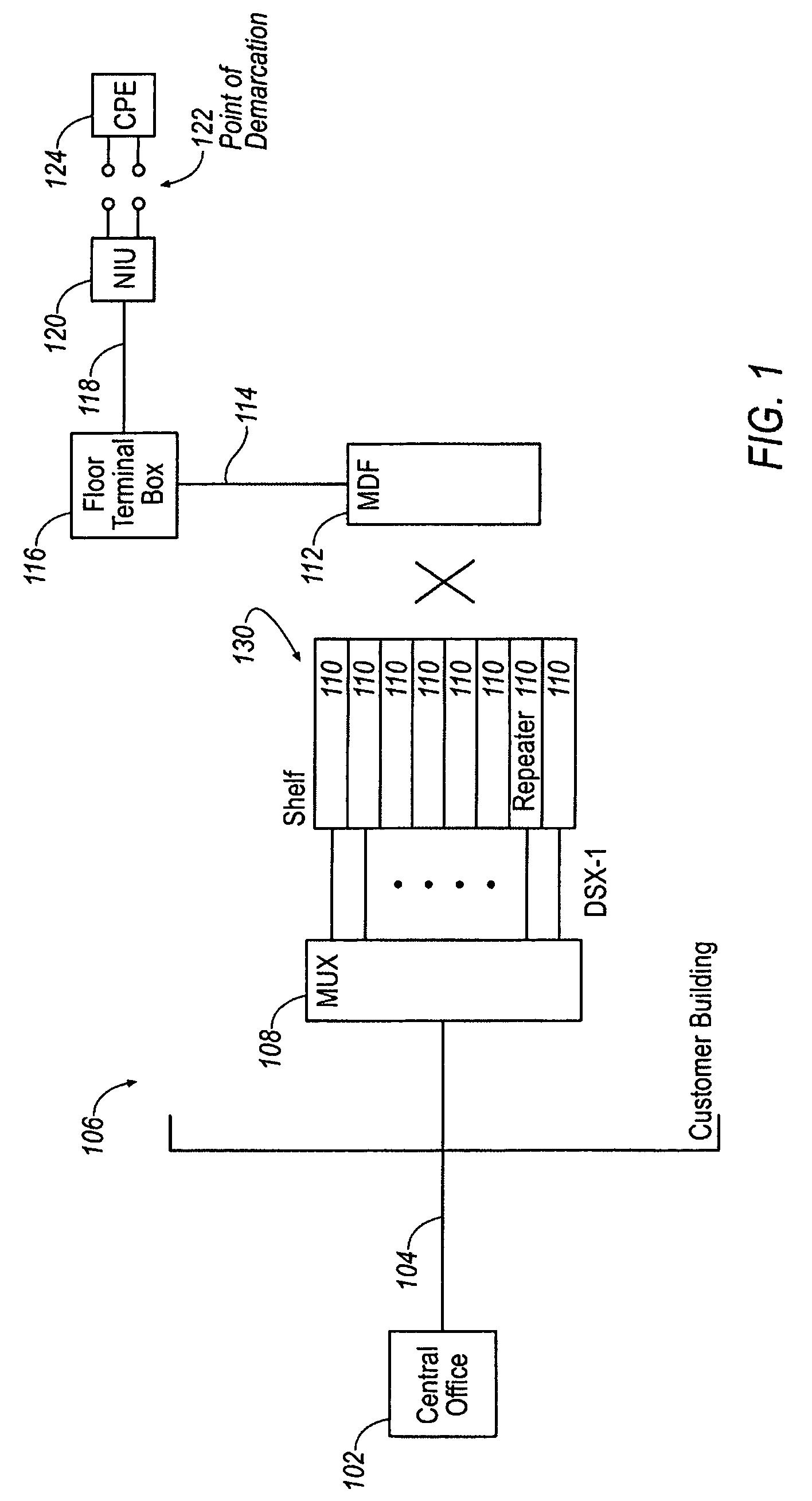
[0022]FIG. 1 illustrates an exemplary environment for certain embodiments of extension repeaters according to the present invention. Transmission of signals from the central office 102 to a customer destination 106 is accomplished over digital line facilities 104. As indicated earlier, these facilities 104 support bi-directional communication and therefore, in practice, transmission of signals from the customer destination 106 to the central office 102 is also accomplished over the facilities 104. These facilities may provide large numbers of telephone lines to high volume customers. Increasingly, these relatively high speed facilities are used to provide dedicated Internet connectivity to the customer's destination 106, to provide wide area intranetwork links, or to provide data intensive services such as video or multimedia services. Throughout the remainder of the present description, the network facilities are assumed to be bi-directional even if not explicitly identified as suc...


PUM


Abstract

An extension repeater which interfaces between a digital service network and a local network span combines extensive diagnostic and operational functions in a single, space-efficient device. The functions include simultaneous loopback capability in both the direction of the digital service network and the local network span, signal regeneration capability in both directions, non-intrusive monitoring connections for each side of the repeater, and visual indicators of the loopback states as well as the framing type of the data received from the digital service network and the local network span. Furthermore, the extension repeater is physically sized and shaped to fit in standard wall-mount telephone equipment shelves in order to provide economical and simplified installation of the repeater at locations outside of a telephone network central switching office.

Description

FIELD OF THE INVENTION[0001]The present invention relates to digital transmission networks and more particularly, to an outside-plant extension repeater for a link of a digital transmission network.BACKGROUND[0002]Since the 1960s, the public switched telephone networks have utilized time-division multiplexed systems to carry both voice and data signals over a digital communications link. One of the earliest and most commonly used carrier systems for such signals is the T-carrier system. The T1 line is probably the most common type of T-carrier in use today. In North America, it typically provides a 4-wire transmission path that transmits bipolar pulse streams at bit rates of 1.544 Mbps. The four wires provide a full-duplex capability with one pair of wires for receiving and another pair for sending at the same time. Originally, the four wires were formed by two pairs of twisted-pair copper wires, but T1 wiring may now also include coaxial cable, optical fiber and other media. Standa...

Claims


Application Information

Patent Timeline
Patent Type & Authority Patents(United States)
IPC IPC(8): H04J1/16
CPCH04B3/36H04M3/30H04M3/40H04Q1/02H04M2203/055
Inventor DEMAKAKOS, WILLIAM N.NEAL, III, FORREST P.
Owner VERIZON PATENT & LICENSING INC
Why Eureka
Try Eureka