Open fiber control for optical transceivers

a technology of optical transceivers and fiber control, applied in the field of optical transceivers, can solve the problems of limiting the usefulness of multi-channel optical transceivers, reducing the power of signals, and the total power transmitted still cannot exceed the eye-safety limits, so as to achieve the effect of increasing the data rate, preserving eye safety, and increasing optical power

Active Publication Date: 2006-08-15
AVAGO TECH INT SALES PTE LTD
View PDF11 Cites 24 Cited by
  • Summary
  • Abstract
  • Description
  • Claims
  • Application Information

AI Technical Summary

Benefits of technology

[0009]In a preferred embodiment, the present invention is implemented by an optical transceiver that uses multiple channel techniques, e.g. multi-channel parallel transmission or WDM. During normal operation, the transceiver transmits all channels at power levels up to maximum eye-safety levels. Although the total optical power transmitted exceeds the eye-safety level, no harm occurs since the connections are intact. When an open fiber is detected, all but one of the channels in the transmitter is disabled. The remaining channel continues transmission at an eye-safe level and is used to detect when the link is reestablished. Once the connection is reestablished, all channels resume normal operation. The ch

Problems solved by technology

Unfortunately, these safety constraints limit the usefulness of multi-channel optical transceivers, which employ techniques such as multi-channel parallel transmission or wavelength division multiplexing (WDM).
These techniques enable transceivers to transmit at higher data rates by using multiple channels, but the total power transmitted still cannot exceed the eye-safety limits.
However, reducing the power of the signals in each channel also reduces the distance the signals can travel without losing integrity.
However, it is difficult to synchroni

Method used


Image

  • Open fiber control for optical transceivers
  • Open fiber control for optical transceivers
  • Open fiber control for optical transceivers

Examples


Embodiment Construction

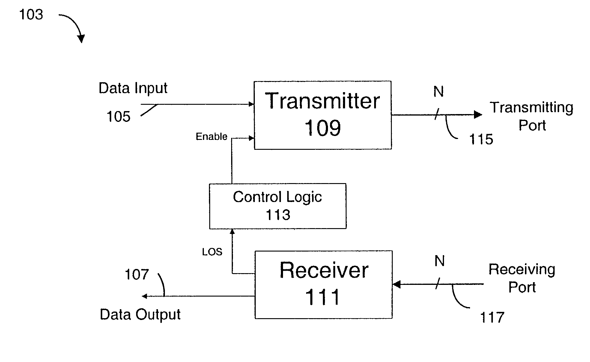
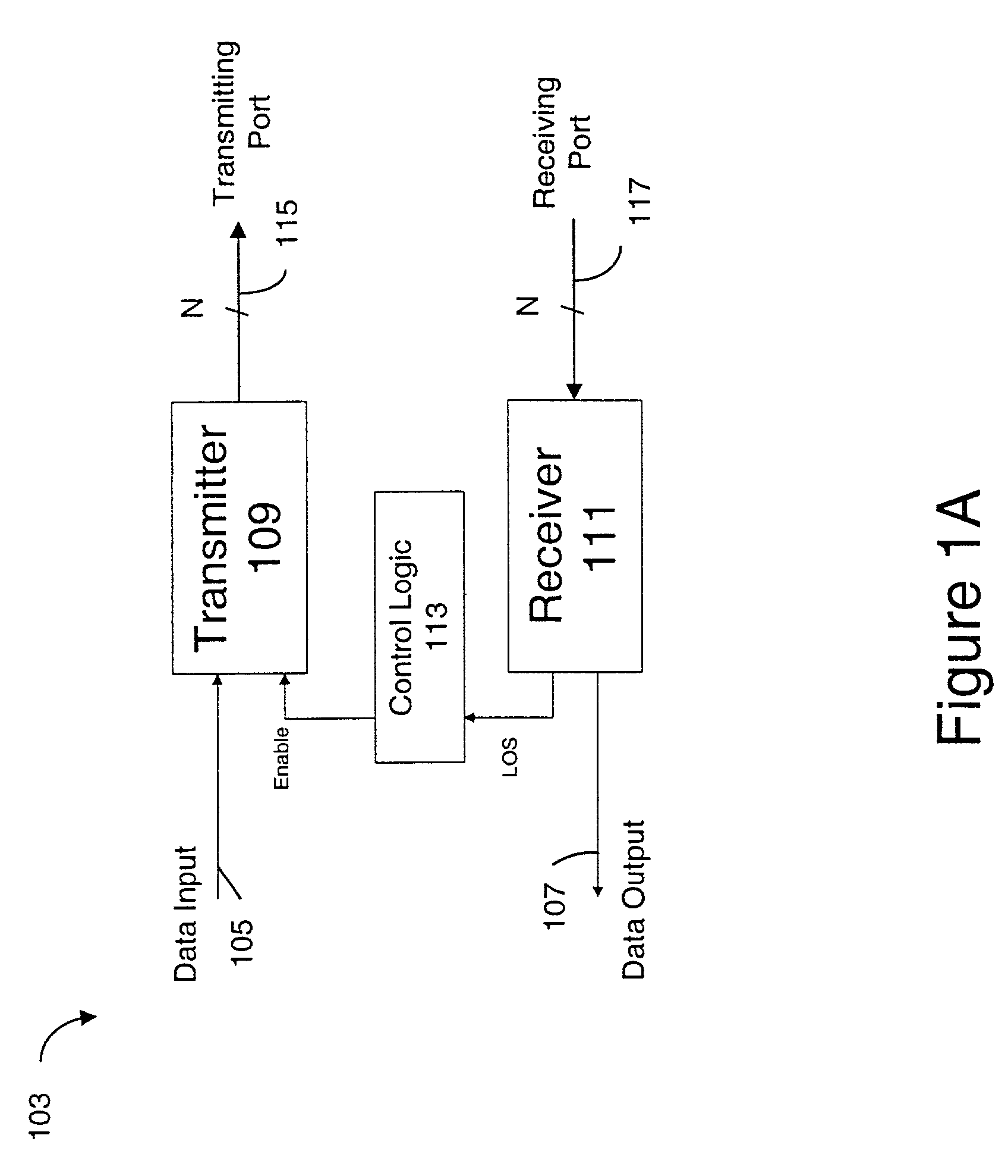
[0017]FIG. 1A is a block diagram showing a preferred embodiment of the present invention. Optical transceiver 103 has a data input 105, a data output 107, a transmitter 109, a receiver 111, and control logic 113. Transmitter 109 transmits N channels at transmitting port 115. Receiver 111 receives N channels at receiving port 117 and determines whether a signal is present. When receiver 111 detects a signal, optical transceiver 103 is properly connected. When no signal is detected, an open fiber exists. Receiver 111 indicates to control logic 113 whether a signal is present by asserting or de-asserting a Loss of Signal (LOS) control line. Control logic 113 enables or disables N−1 channels of transmitter 109 with an Enable control line.

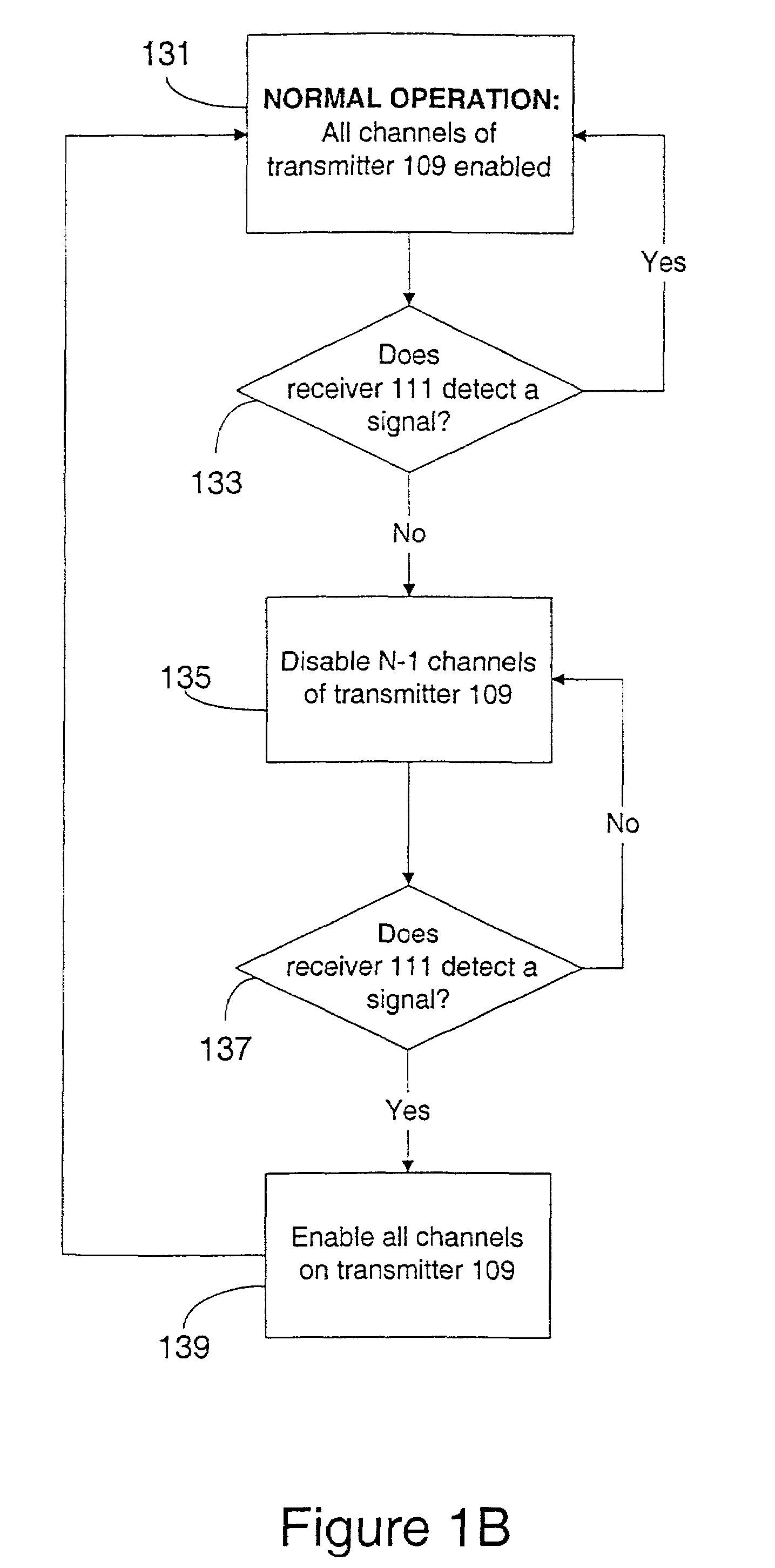
[0018]FIG. 1B is a flow chart describing OFC in optical transceiver 103, according to the present invention. During normal operation in step 131, the optical transceiver 103 has an intact connection to an optical network, and all N channels of transmitt...


PUM


Abstract

The present invention implements open fiber control in an optical transceiver. During normal operation, the transceiver transmits signals through a connection to an optical network. When the connection is intact, the total power transmitted can be greater than the eye-safety limit. When the connection breaks, the transceiver detects the loss of signal and disables transmissions over all channels except for one. The transceiver continues transmission on the single enabled channel at an eye-safe level. When the connection is fixed and a signal reappears, the transceiver detects the signal reappearance and re-enables all channels that had previously been disabled. By allowing the transceiver to transmit with greater optical power when the connection is intact, an increased data rate and longer transmission distances can be achieved. At the same time, safety is preserved, because transmissions drop to acceptable power levels whenever a break is detected.

Description

FIELD OF THE INVENTION[0001]The invention is directed towards optical transceivers, and more specifically, towards the open fiber control of optical transceivers.BACKGROUND OF THE INVENTION[0002]Optical transceivers must be designed to transmit signals with sufficient power to meet the transmission distance and performance requirements of the system. At the same time, standard bodies such as the International Electrotechnical Commission (IEC) and the Center for Devices and Radiological Health (CDRH) have imposed limits on the magnitude of optical power that can be transmitted in a link between two transceivers, to protect the human eye in case of an open fiber. An open fiber is any discontinuity in the signal path that causes the signal light to escape into the open, e.g. a physical break in the optical fiber or an unplugged connector. Usually, an open fiber is the result of an unplugged connector. Unfortunately, these safety constraints limit the usefulness of multi-channel optical...

Claims


Application Information

Patent Timeline
IPC IPC(8): H04B10/08H04B10/02H04B10/04H04B10/06H04B10/14H04B10/24H04B10/26H04B10/43
CPCH04B10/0799H04B10/40H04B2210/08
Inventor CUNNINGHAM, DAVID GMILLER, FREDERICKWANG, JINGYUN, JANET
Owner AVAGO TECH INT SALES PTE LTD
Why Eureka
Try Eureka