Tunable channel spacing for wavelength division multiplexing (WDM) transport system

a transport system and wavelength division multiplexing technology, applied in the field of optical transport systems, can solve the problems of limiting the traffic that can be carried by the network, waste of unused channel capacity, etc., and achieve the effect of improving the optical transport system and maximizing the entire working bandwidth of the transport system

Inactive Publication Date: 2006-08-15
FUJITSU LTD
View PDF20 Cites 31 Cited by
  • Summary
  • Abstract
  • Description
  • Claims
  • Application Information

AI Technical Summary

Benefits of technology

[0012]Another technical advantage of the present invention includes providing an improved optical transport system. In a particular embodiment, the optical transport system supports mixed bit rate signals and may dynamically adjust channel spacing to account for varying bit rates of the signals. In this way, the entire working bandwidth of the transport system may be efficiently utilized.
[0013]Still another technical advantage of the present invention includes providing an improved WDM multiplexer and WDM demultiplexer. In a particular embodiment, tunable filters are used in the WDM multiplexer and the WDM demultiplexer to vary the spectrum width of the channels, and thus the channel spacing. Because the width of channel spacings is variable, different amounts of data may be modulated onto a signal within a given channel, and a bandwidth allocated to the channel can be dynamically changed to accommodate an increase or a decrease in bit rate. This allows for the most efficient use of the system by allocating narrow bandwidth channels to low bit rate signals and wider bandwidth channels to higher bit rate signals.
[0014]Still another technical advantage of the present invention includes providing an improved transponder for WDM systems. In a particular embodiment, the transponder is a bit-to-bit transponder with wavelength conversion capability and includes selectable clock sources to support mixed bit rate channels. Thus, the transponder may be used in connection with different channels having different bit rates and may be dynamically adjusted to support a single channel with a changing bit rate.

Problems solved by technology

Unused channel capacity is wasted and limits traffic that can be carried by the network.

Method used


Image

  • Tunable channel spacing for wavelength division multiplexing (WDM) transport system
  • Tunable channel spacing for wavelength division multiplexing (WDM) transport system
  • Tunable channel spacing for wavelength division multiplexing (WDM) transport system

Examples


Embodiment Construction

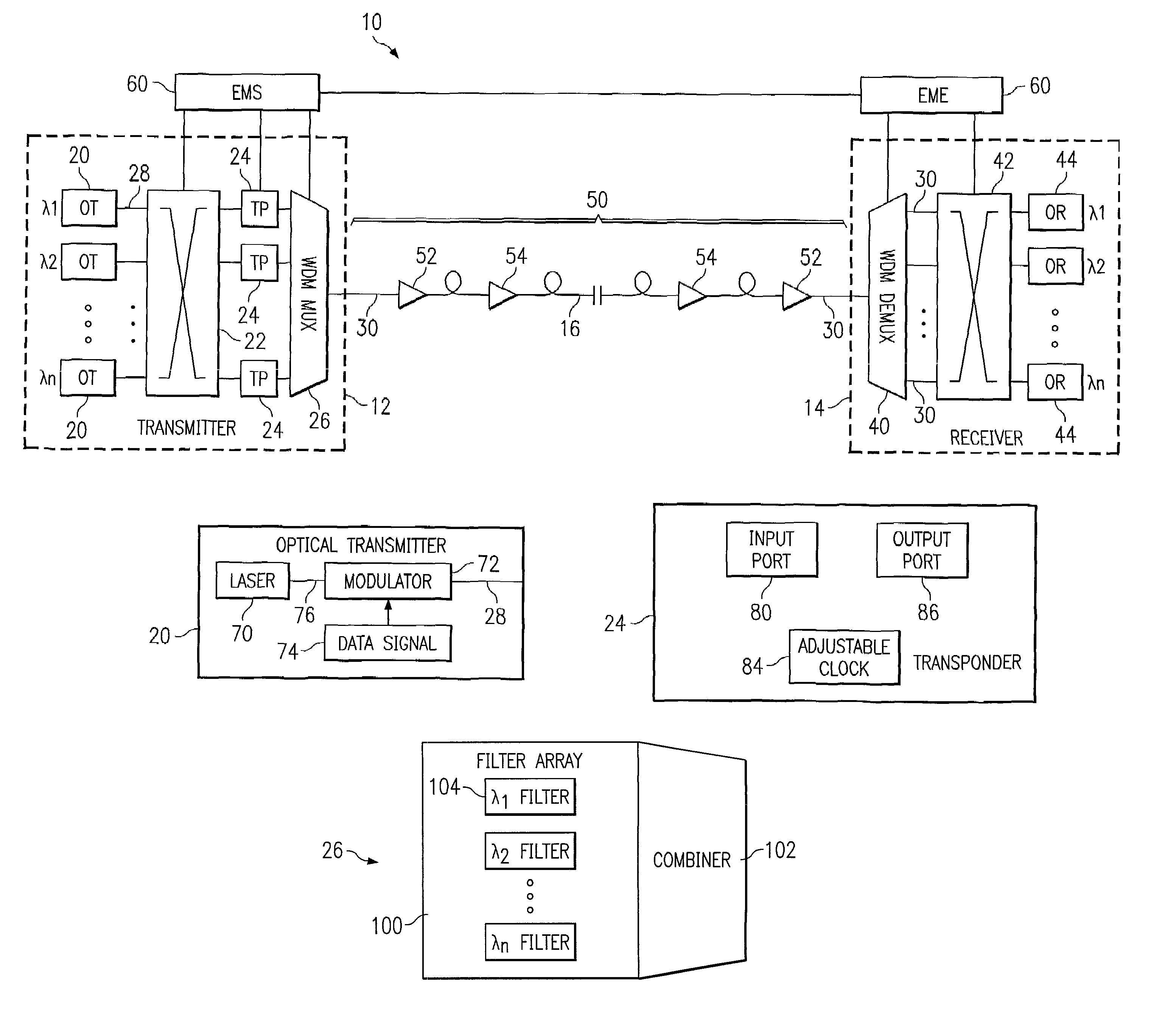
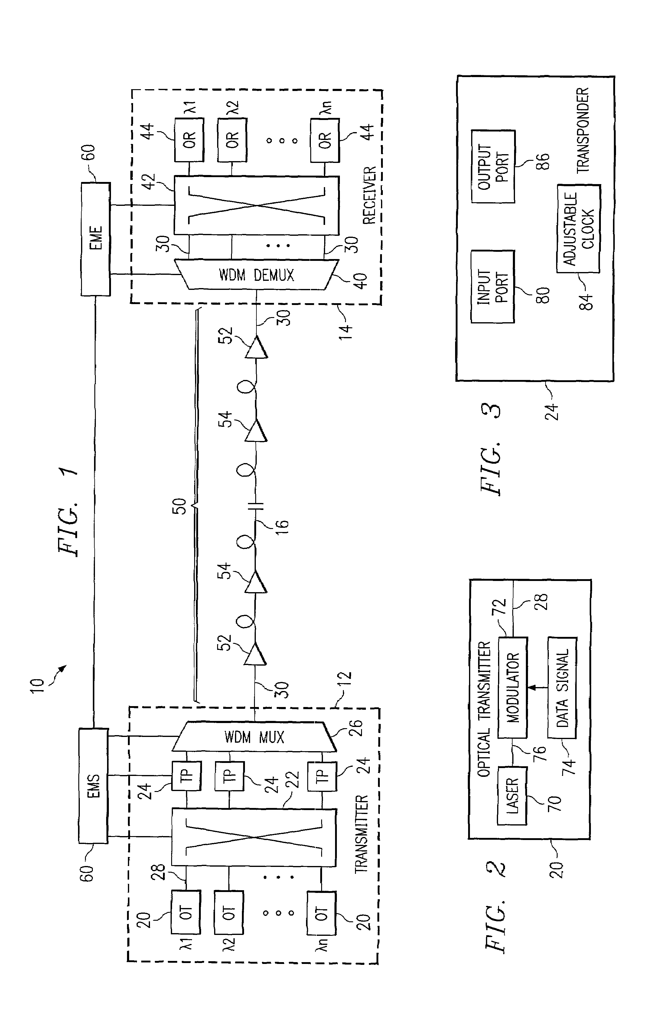
[0027]FIG. 1 illustrates an optical transport system 10 in accordance with one embodiment of the present invention. In this embodiment, the optical transport system 10 is a wavelength division multiplexing (WDM) system in which a number of optical channels are carried over a common path at disparate wavelengths. The WDM system 10 may comprise a dense WDM (DWDM) and other suitable multi-channel transport system. The optical transport system 10 may be used in a short-haul metropolitan network, a long-haul intercity network or any other suitable network or combination of networks.

[0028]Referring to FIG. 1, the WDM system 10 includes a WDM transmitter 12 at a source end point and a WDM receiver 14 at a destination end point coupled together by an optical link 16. The WDM transmitter 12 transmits data in a plurality of optical signals, or channels, over the optical link 16 to the remotely located WDM receiver 14. As described in more detail below, the spectrum width, or spacing, of the c...


PUM


Abstract

A method and system for tuning channel spacing for a wavelength division multiplexing (WDM) transport system includes determining a spectrum width for a channel. A bandwidth of a group of base channels covering the spectrum width for the channel is allocated to the channel. A passband of a channel filter at a center frequency of the group is adjusted to correspond to the spectrum width of the channel.

Description

CROSS REFERENCE TO RELATED APPLICATION[0001]This application is a continuation-in-part of U.S. application Ser. No. 09 / 633,005, filed Aug. 4, 2000, by David G. Way and entitled “Transport System with Tunable Channel Spacing DWDM”.TECHNICAL FIELD OF THE INVENTION[0002]The present invention relates generally to optical transport systems, and more particularly to a method and system for tuning channel spacing for a wavelength division multiplexing (WDM) transport system.BACKGROUND OF THE INVENTION[0003]Telecommunications systems, cable television systems and data communication networks use optical networks to rapidly convey large amounts of information between remote points. In an optical network, information is conveyed in the form of optical signals through optical fibers. Optical fibers are thin strands of glass capable of transmitting the signals over long distances with very low loss.[0004]Optical networks often employ wavelength division multiplexing (WDM) to increase transmissio...

Claims


Application Information

Patent Timeline
Patent Type & Authority Patents(United States)
IPC IPC(8): H04B10/00H04B10/155H04J14/02
CPCH04B10/50H04J14/02H04J14/0246H04J14/0227H04J14/0279
Inventor WAY, DAVID G.
Owner FUJITSU LTD
Why Eureka
Try Eureka