Multiple venture tube gas fuel injector for a combustor

a gas fuel injector and multi-venture technology, which is applied in the direction of machines/engines, combustion types, lighting and heating apparatus, etc., can solve the problems of increasing the amount of steam injection, the amount of nox reduction desired, and the maximum flame temperature of the combustor at the cost of thermodynamic efficiency. , the effect of reducing the maximum flame temperatur

Inactive Publication Date: 2006-08-22
GENERAL ELECTRIC CO
View PDF17 Cites 34 Cited by
  • Summary
  • Abstract
  • Description
  • Claims
  • Application Information

AI Technical Summary

Problems solved by technology

Prior-art techniques for accomplishing such reduced emissions almost invariably result in reduced thermodynamic efficiency or substantially increased capital costs.
Injection of steam into the combustor reduces the maximum flame temperature in the combustor at the cost of thermodynamic efficiency.
The amount of steam injection, and its attendant costs, rises with the amount of NOx reduction desired.
Some states and foreign countries have announced targets for NOx reduction that infer such large quantities of steam that this solution appears less desirable for future systems.
This technique, although successful in reducing NOx compounds to target levels, requires substantial additional capital outlay for the catalyst bed, a larger exhaust system to provide room for the large catalyst bed and spray bars to deliver the reagent into the exhaust stream.
The on-going cost of large quantities of the reagent must also be borne.
One problem, not completely solved by the referenced prior-art patents, is attaining a uniform flow field of fuel-air mixture across the entire face of a catalyst bed.
That is, the fuel-air mixture and the gas velocity vary across the face of the catalyst bed, resulting in uneven combustion across the catalyst.
This reduces combustor efficiency and can permit unburned hydrocarbons to escape to the exhaust.
These large and irregular recirculation zones result in poor flameholding resistance at the exit of the premixer.

Method used


Image

  • Multiple venture tube gas fuel injector for a combustor
  • Multiple venture tube gas fuel injector for a combustor
  • Multiple venture tube gas fuel injector for a combustor

Examples


Embodiment Construction

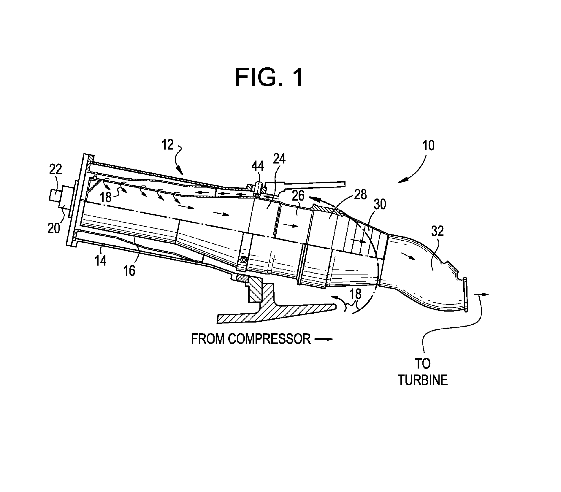
[0022]A typical gas turbine engine employs a plurality of parallel combustors disposed in a circle about an axis. A fuel-air mixture is burned in each combustor to produce a hot, energetic flow of gas. The gas from each combustor travels through a transition piece wherein the gas flow is changed from a generally circular field to a field approximating an arc of a circle. The outlets of all of the transition pieces are arranged to form a full circle leading to turbine blades of the machine. All of the above is conventional and does not require further description to enable full understanding by one skilled in the art. Accordingly, attention is focused in the remainder of the present description on a single combustor, it being understood that all combustors in a gas turbine engine are substantially identical to the one described. Only those additional portions of a gas turbine engine required for an understanding of the environment in which the combustor operates are shown and describ...


PUM


Abstract

A gas fuel injector includes a first header plate; a second header plate spaced downstream from the upstream header plate; and a plurality of venturi tubes arranged in rows and sealably secured to the first and second header plates. Each of the venturi tubes includes an inlet section, a throat section and an exit. The exit is shaped into a pattern that reduces space between each of the venturi tubes at the exit of each of the plurality of venturi tubes.

Description

BACKGROUND OF THE INVENTION[0001]The present invention relates to a gas fuel injector for a combustor in an engine.[0002]A present thrust of gas-turbine engine technology seeks to attain reduced emissions of nitrogen-oxygen and unburned hydrocarbon compounds (NOx and UHC, respectively). Prior-art techniques for accomplishing such reduced emissions almost invariably result in reduced thermodynamic efficiency or substantially increased capital costs.[0003]NOx compounds are produced by reaction of the nitrogen in the air at elevated temperatures conventionally found in the combustors of a gas turbine engine. NOx formation can be reduced by reducing the maximum flame temperature in the combustor. Injection of steam into the combustor reduces the maximum flame temperature in the combustor at the cost of thermodynamic efficiency. Penalties must also be paid in water use, and water treatment capital and operating costs. The amount of steam injection, and its attendant costs, rises with the...

Claims


Application Information

Patent Timeline
Patent Type & Authority Patents(United States)
IPC IPC(8): F02C1/00F02G3/00
CPCF23D23/00F23R3/40F23R3/286Y02E20/34
Inventor DINU, CONSTANTINFARRELL, THOMAS RAYMONDGORDON, KEVIN M.STOREY, JAMES MICHAELVENKATARAMAN, KRISHNA KUMAR
Owner GENERAL ELECTRIC CO
Why Eureka
Try Eureka