Wall mount fiber optic connector and associated method for forming the same

a fiber optic connector and wall mount technology, applied in the field of connectors, can solve the problems of increasing the cost, weight and complexity of each electronic system, adding to the overall volume of the system, and not being particularly well suited to harsh environments

Active Publication Date: 2006-08-22
MOOG INC
View PDF23 Cites 105 Cited by
  • Summary
  • Abstract
  • Description
  • Claims
  • Application Information

AI Technical Summary

Benefits of technology

[0008]In view of the foregoing background, it is therefore an object of the present invention to provide an active wall mount fiber optic connector that is reliable in harsh environments.
[0012]Each respective biasing member may comprise a spring under compression. The wall mount fiber optic connector may further comprise a spring plate between the flexible circuits and the O / E converters. Each spring is between the spring plate and a corresponding O / E converter. Since each O / E converter is urged towards a corresponding ferrule-receiving passageway, this advantageously allows independent movement with respect to one another, which is beneficial when operating in a harsh environment. The axial movement of each O / E converter also allows the ferrules in the mating plug connector portion to be fixed.
[0013]Each O / E converter also comprises a plurality of conductive leads extending rearwardly therefrom and being coupled to a corresponding flexible circuit. The spring plate may include a plurality of openings therein aligned with the plurality of conductive leads. Since each O / E converter is connected to a flexible circuit that is separate from the other flexible circuits, this advantageously ensures electrical continuity during axial movement of the O / E converters, which is also beneficial when operating in a harsh environment.

Problems solved by technology

When routing each optical fiber from the wall mount fiber optic connector to an appropriate O / E converter within the housing, several problems are encountered.
The use of an optical fiber backplane within the housing adds to the cost, weight and complexity of each electronic system, as well as to the overall volume of the system.
However, the fiber optic connector in Kurashima et al. is not a wall mount fiber optic connector.
Unfortunately, this active fiber optic connector is not particularly well suited for harsh environments.
Maintaining alignment of the optical fibers in the plug connector portion with the O / E converters in the receptacle connector portion is a problem under harsh environments, which are typically encountered in various types of air, space, land and sea-based platforms.

Method used


Image

  • Wall mount fiber optic connector and associated method for forming the same
  • Wall mount fiber optic connector and associated method for forming the same
  • Wall mount fiber optic connector and associated method for forming the same

Examples


Embodiment Construction

[0026]The present invention will now be described more fully hereinafter with reference to the accompanying drawings, in which preferred embodiments of the invention are shown. This invention may, however, be embodied in many different forms and should not be construed as limited to the embodiments set forth herein. Rather, these embodiments are provided so that this disclosure will be thorough and complete, and will fully convey the scope of the invention to those skilled in the art. Like numbers refer to like elements throughout, and prime notation is used to indicate similar elements in alternative embodiments.

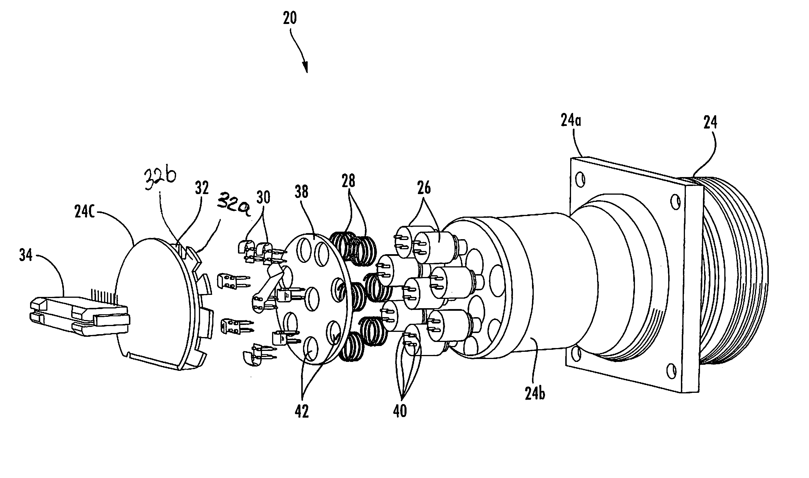
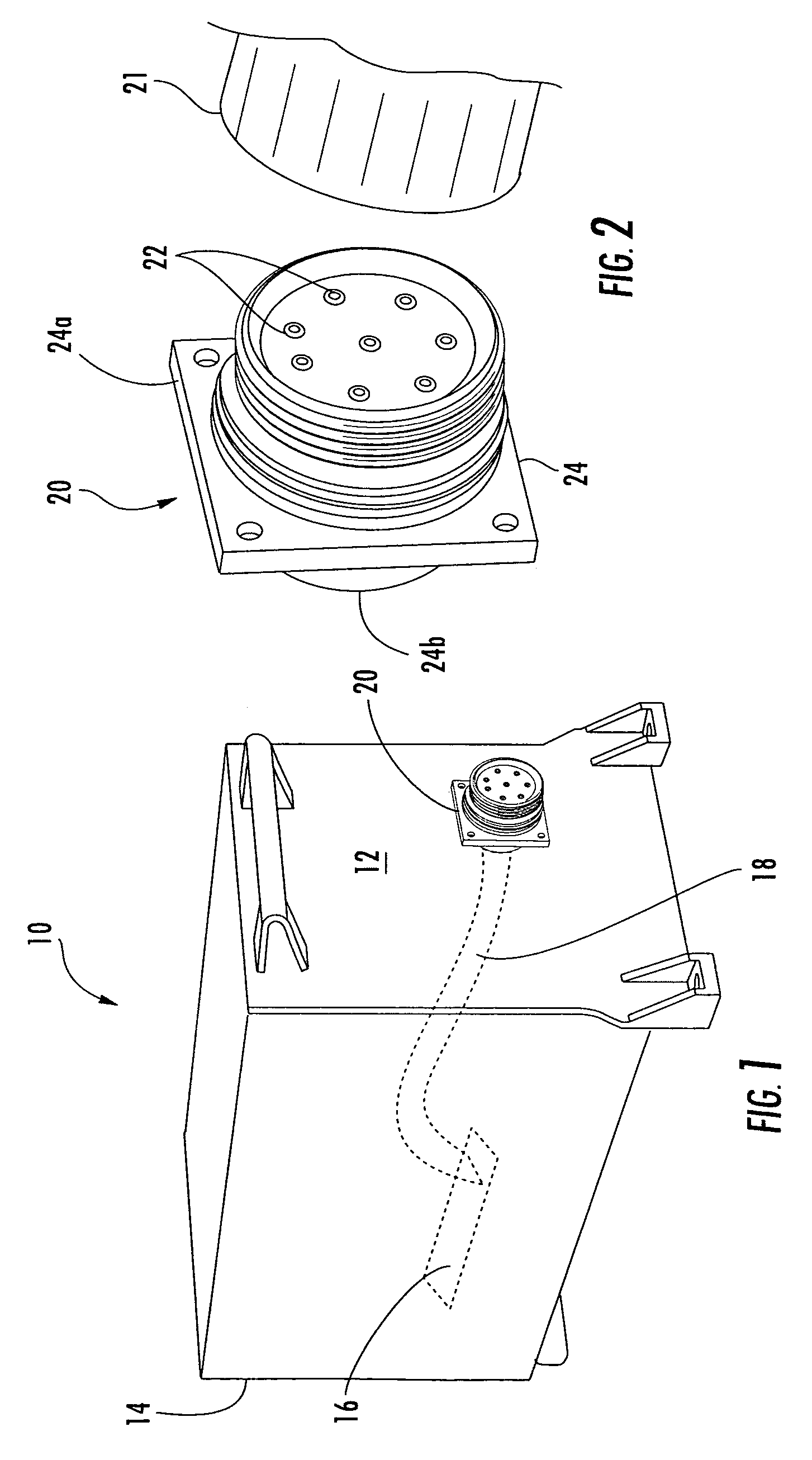
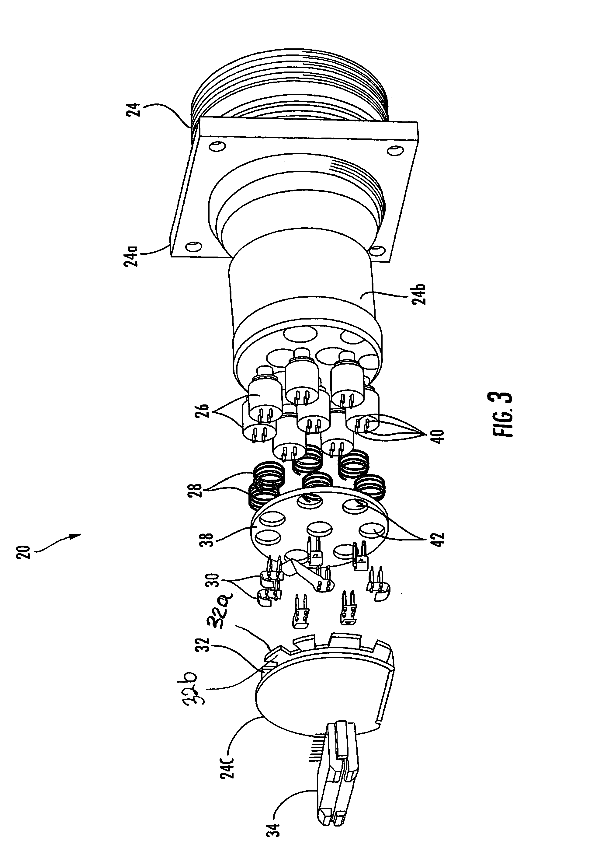
[0027]An electronic system 10 having at least one wall mount fiber optic connector 20 mounted to a wall 12 thereof will initially be discussed with reference to FIGS. 1 and 2. The electronic system 10 comprises a housing or system chassis 14, and the housing carries an electrical circuit 16 which interfaces with the wall mount fiber optic connector 20 via an electrical cabl...


PUM


Abstract

A wall mount fiber optic connector includes a connector body portion to be mounted on a wall of an electronic system, and the connector body portion has ferrule-receiving passageways therein. Opto-electronic (O / E) converters are coupled to the ferrule-receiving passageways, with each O / E converter being associated with a respective ferrule-receiving passageway. Biasing members are coupled to the O / E converters, with each biasing member urging a respective O / E converter forward. The wall mount fiber optic connector also includes flexible circuits, with each flexible circuit having a first end coupled to a respective O / E converter. A printed circuit board is coupled to second ends of the flexible circuits. An electrical connector portion is carried by the connector body portion and is coupled to the printed circuit board.

Description

FIELD OF THE INVENTION[0001]The present invention relates to the field of connectors, and more particularly, to a wall mount fiber optic connector.BACKGROUND OF THE INVENTION[0002]Fiber optic cabling is used in various types of air, space, land and sea-based platforms to provide high-speed data communications for on-board electronic systems, such as radar and mission control computer systems. In a typical wall mount fiber optic connector, the receptacle connector portion is connected to the wall mount of the electronic system and extends rearwardly within an overall housing or system chassis of the electronic system. The mating plug connector portion is removably positioned into the receptacle connector portion from the outside of the housing.[0003]Such typical wall mount fiber optic connectors are passive connectors, and consequently, these connectors merely pass the optical signals through the connector. Passive connectors require fiber optic cabling within the electronic system f...

Claims


Application Information

Patent Timeline
Patent Type & Authority Patents(United States)
IPC IPC(8): G02B6/36G02B6/38G02B6/42
CPCG02B6/4292G02B6/4201G02B6/3821G02B6/3897G02B6/4246G02B6/428G02B6/4283G02B6/4281G02B6/4284G02B6/42
Inventor LORD, RANDAL BRUCESCHARF, ROBERT MARC
Owner MOOG INC
Why Eureka
Try Eureka