System and method of surge limit control for turbo compressors

a turbo compressor and surge limit technology, which is applied in the direction of machines/engines, positive displacement liquid engines, engine starters, etc., can solve the problems of damage to turbo compressors, adverse impact on the overall efficiency of turbo compressors, and inadequate protection, so as to minimize the recurrence of surge events

Active Publication Date: 2006-08-22
CONTINUOUS CONTROL SOLUTIONS
View PDF19 Cites 60 Cited by
  • Summary
  • Abstract
  • Description
  • Claims
  • Application Information

AI Technical Summary

Benefits of technology

[0013]The present invention has been described in detail for use with turbo compressors having constant gas composition control systems that minimizes the recurrence of surge events. However, the present invention can be practiced for turbo compressor's with variable gas composition, when a software gas composition sensor or an online gas analyzer is available.
[0014]Moreover, the present invention offers the user a way to control the anti-surge valve by providing a closed proportional-integral-derivative (PID) loop that monitors the compressor's current pressure ratio and compares the same to the compressor's pressure ratio at surge limit conditions. The anti-surge valve is opened when the compressor's pressure ratio falls within a predetermined safety margin. The suggested size of the safety margin is approximately 3% to 5% of the total span of the compressor's pressure ratio and covers approximately 1% of any setting of the polytrophic exponent.

Problems solved by technology

Surging can significantly damage a turbo compressor and therefore, control systems have been developed to monitor a turbo compressor's performance.
If recycling occurs too extensively, it will have an adverse impact on the overall efficiency of the turbo compressor.
If recycling is not properly controlled, there may be inadequate protection against surge and the potential damage it may cause to the turbo compressor.
A compressor's surge limit, displayed in coordinates of the reduced flow rate (Qr) and the reduced head (Hr) is often very difficult to accurately characterize.
This difficulty arises from the quality of current compressor flow measurement methods.
The level of difficulty increases further when multistage compressors and compressors with side streams are employed.

Method used


Image

  • System and method of surge limit control for turbo compressors
  • System and method of surge limit control for turbo compressors
  • System and method of surge limit control for turbo compressors

Examples


Embodiment Construction

[0022]The present invention will be described as it applies to its preferred embodiment. It is not intended that the present invention be limited to the described embodiment. It is intended that the invention cover all modifications and alternatives which may be included within the spirit and scope of the invention.

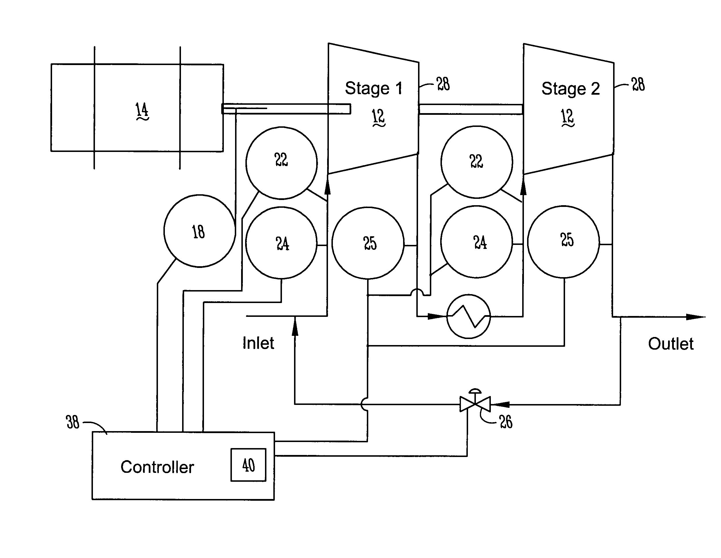
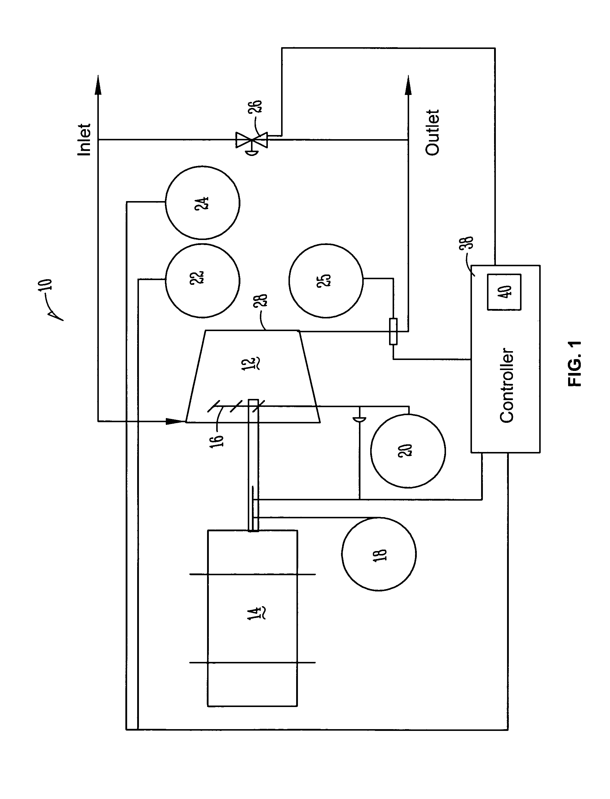
[0023]Now, referring to the drawings, FIG. 1 shows a typical turbo compressor system 10 according to the present invention which usually includes a turbo compressor 12, a variable speed drive 14 and guide vanes 16. The operating conditions of the turbo compressor 12 are preferably monitored using a rotational speed transmitter 18, a guide vane position transmitter 20, an inlet pressure transmitter 22, an inlet temperature transmitter 24 and an outlet pressure transmitter 25. To prevent the compressor 12 from surging, an anti-surge valve 26 is connected to the output 28 of the compressor 12.

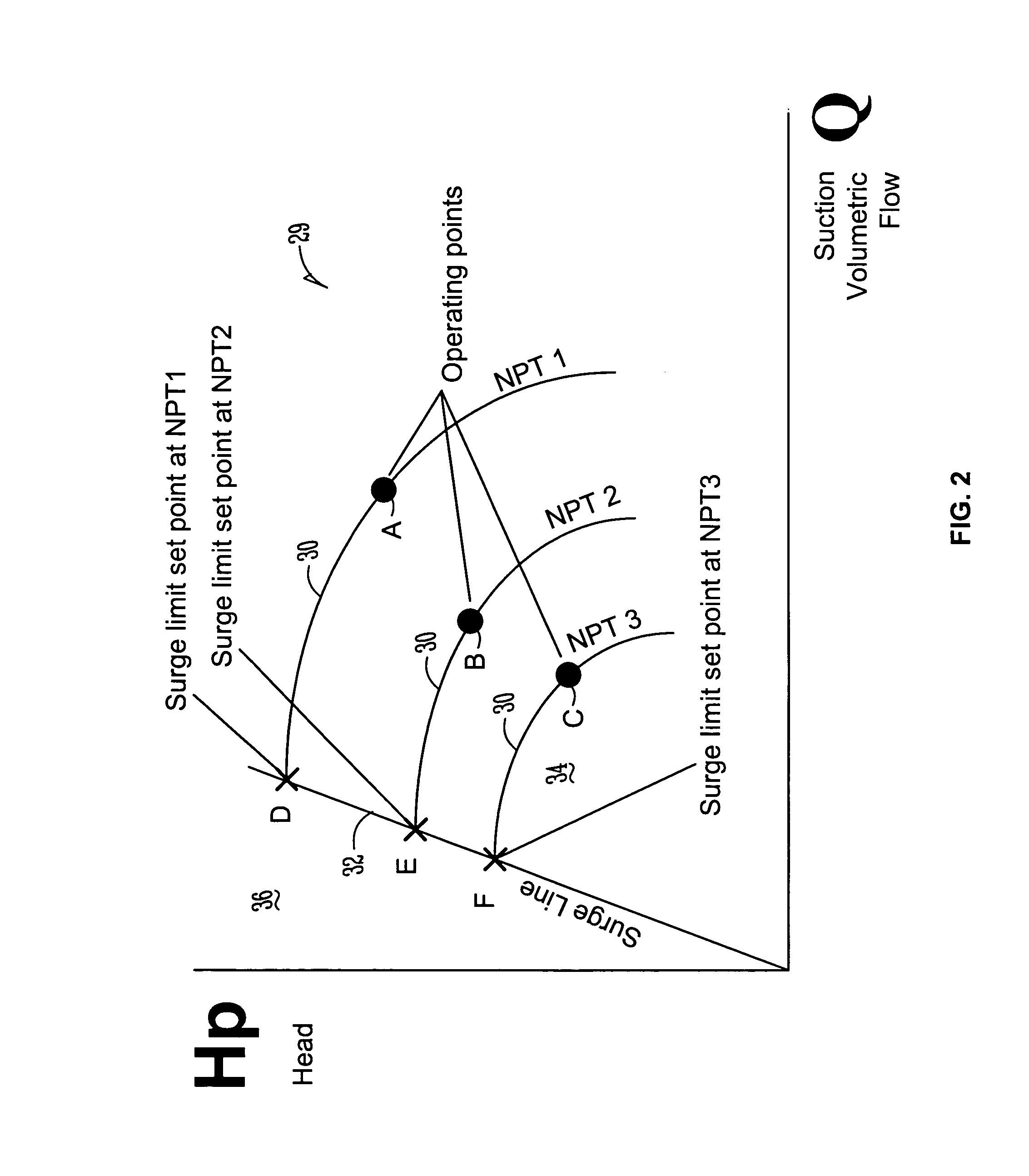
[0024]As is shown in FIG. 2, a typical compressor will be provided with a compresso...


PUM


Abstract

A system and method of surge limit control for turbo compressors including a turbo compressor having an inlet and an outlet, an anti-surge valve, a variable speed drive to operate the compressor, a rotational speed transmitter, an inlet temperature transmitter, an inlet pressure transmitter, an outlet pressure transmitter and/or guide vanes, and a controller, the controller including a PID control module wherein the computer uses information from the transmitters to continuously calculate a pressure ratio of the compressor at the compressor's current operational speed and compare it to the compressor's calculated pressure ratio at surge limit conditions. A computer generates a control signal for determining when to open the anti-surge valve if the pressure ratio of the compressor at the compressor's current operational speed guide vanes are within a user defined safety margin to the calculated pressure ratio at surge limit conditions.

Description

FIELD OF THE INVENTION[0001]The present invention relates to a method of controlling turbo compressors, and more particularly to a new and useful method of efficiently and effectively controlling turbo compressors in a manner that minimizes the risks of turbo compressors reaching their surge limit.BACKGROUND OF THE INVENTION[0002]Unstable flow conditions within a turbo compressor can arise from any number of changing process conditions. When this occurs and reduces the flow of gasses with an increase in the specific mechanical energy (polytrophic) of the gas stream, the turbo compressor may surge. Surging can significantly damage a turbo compressor and therefore, control systems have been developed to monitor a turbo compressor's performance.[0003]Should the performance levels drop to a potential surge situation, the control systems must open an anti-surge valve to recycle or blow off an additional portion of the gas flow. If recycling occurs too extensively, it will have an adverse...

Claims


Application Information

Patent Timeline
Patent Type & Authority Patents(United States)
IPC IPC(8): F04D27/02F04B49/00F04D27/00
CPCF04D27/0284
Inventor SHAPIRO, VADIM
Owner CONTINUOUS CONTROL SOLUTIONS
Why Eureka
Try Eureka