Heat-dissipating fan

a fan and fan body technology, applied in the direction of positive displacement liquid engines, piston pumps, liquid fuel engines, etc., can solve the problems of increased friction coefficient, short service life, louder mechanic noise, etc., and achieve low friction, low energy consumption, and low operation noise

Inactive Publication Date: 2006-08-22
ACT RX TECH CORP
View PDF9 Cites 3 Cited by
  • Summary
  • Abstract
  • Description
  • Claims
  • Application Information

AI Technical Summary

Benefits of technology

[0006]It is therefore an object of the invention to provide a heat-dissipating fan that can provide advantages such as a low friction, a lower operation noise, a low energy consumption, a high performance and a high stability due to the configuration of the bearing and the lines of magnetic force induced by the silicon steel sheet and the magnetic bar.
[0007]In order to achieve the above and other objectives, a heat-dissipating fan of the invention includes an axle, a bearing, a rotor and a stator. The axle and the bearing are made of a ceramic material, which provides anti-corrosion, anti-oxidation and anti-erosion properties. The axle is a cylinder having a pointed or rounded tip, and is located inside the rotor. The bearing is a hollow cylinder located inside the stator. The bearing is provided with a central hole through which the axle penetrates to contact the bearing. The bearing shares the weight load of the rotor from the axle and provides anti-dust and anti-oil leakage advantages. A magnetic force center of the silicon steel sheet is at a level lower than that of the magnetic bar to generate radial and axial force components, allowing stable rotation of the rotor.

Problems solved by technology

Consequently, the bearing 7 becomes elliptic or irregular, which increases the friction coefficient, and causes erratic running of the motor, a louder mechanic noise and a shorter service life.
Furthermore, the type of conventional heat-dissipating fan is not suitable for use in portable products that are usually used in different positions and orientations.

Method used


Image

  • Heat-dissipating fan
  • Heat-dissipating fan
  • Heat-dissipating fan

Examples


Embodiment Construction

[0018]Wherever possible in the following description, like reference numerals will refer to like elements and parts unless otherwise illustrated.

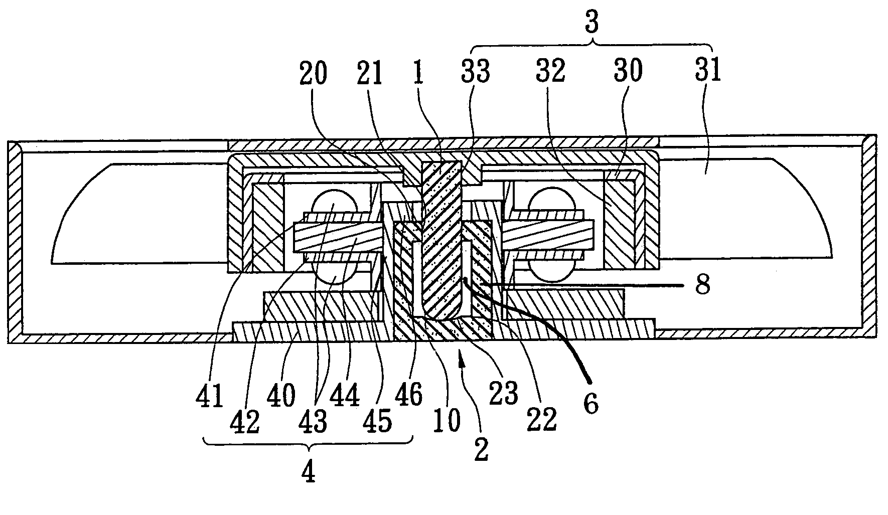
[0019]Referring to FIG. 2 and FIG. 3, the invention provides a heat-dissipating fan including an axle 1, a bearing 2, a rotor 3 and a stator 4.

[0020]The axle 1 is a cylinder made of, for example, ceramic material. The axle 1 has a pointed or rounded tip 10.

[0021]The bearing 2 is a hollow cylinder having a top side and a bottom side 22, for example, integrally formed of ceramic material or alloy. A central hole 21 is formed through the top side 20 of the bearing 2. A recess 23 is formed at central location of an interior of the bottom side 22 of the bearing 2, directly under the central hole 21.

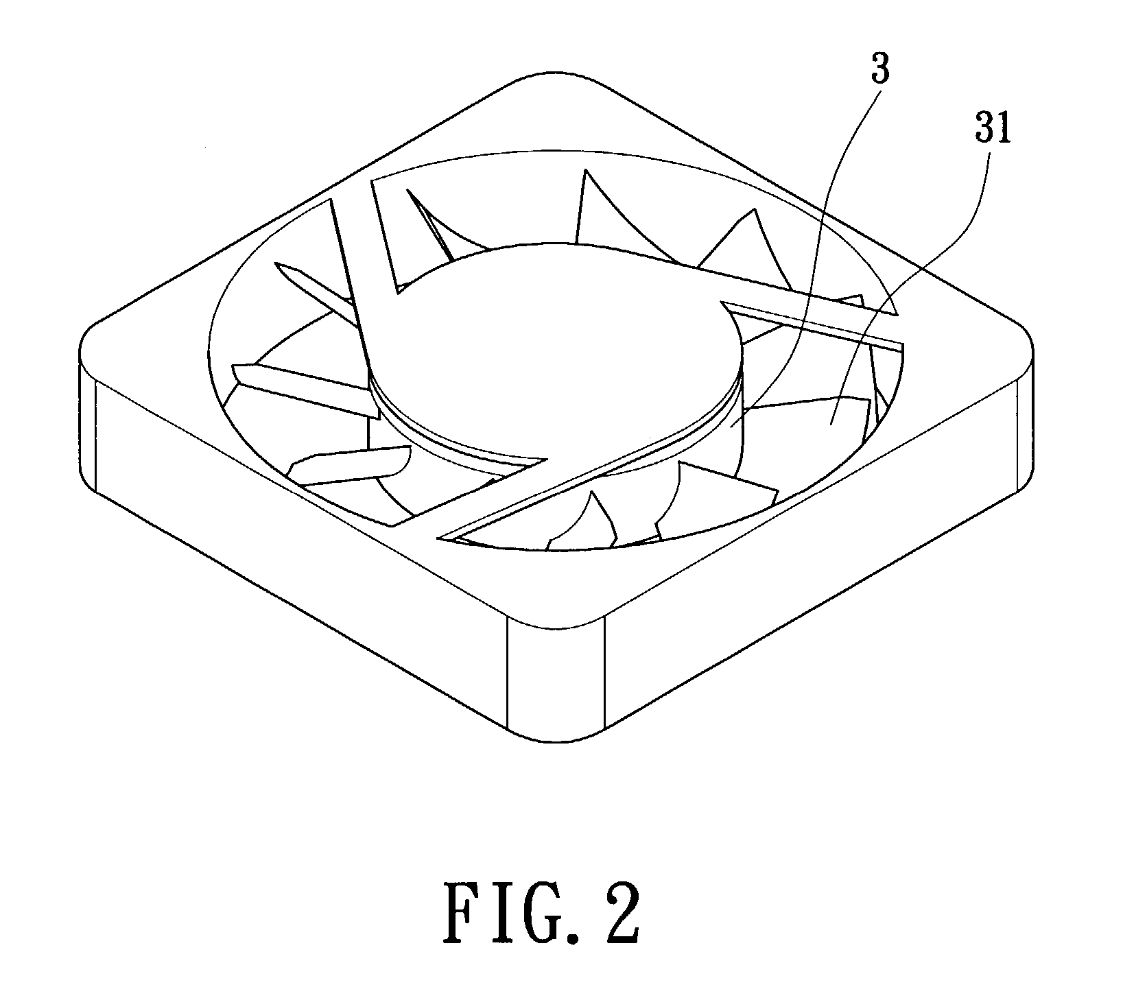
[0022]The rotor 3 includes a motor casing 30, a plurality of blades 31 and a magnetic bar 32. The motor casing 30 is a casing having a down-facing opening and a blind hole 33 at a central location of an interior of the casing 30 for accommodating the ...


PUM

PropertyMeasurementUnit
friction coefficientaaaaaaaaaa
cylindrical shapeaaaaaaaaaa
diameteraaaaaaaaaa

Abstract

A heat-dissipating fan of the invention has an axle, a bearing, a rotor and a stator. The axle and the bearing are made of a ceramic material, and are located at a central location of the rotor and the stator. The bearing is a hollow cylinder integrally formed into a single body, and has a central hole and a recess at its bottom. The axle penetrates through the central hole of the bearing to contact the recess. A magnetic force center of the silicon steel sheet is at a level lower than that of the magnetic bar to generate radial and axial force components, allowing stable rotation of the rotor. The heat-dissipating fan of the invention provides advantages such as low friction, lower noise, low energy consumption, high performance and high stability.

Description

BACKGROUND OF THE INVENTION[0001]1. Field of the Invention[0002]The invention relates to a heat-dissipating fan, and more particularly, to a heat-dissipating fan suitable for use in an electrical appliance such as a personal computer.[0003]2. Description of the Related Art[0004]As the performance of technical devices such as an electric appliance progresses, issues related to heat dissipation in highly integrated devices are more critical. FIG. 1 is a cross-sectional view of a motor 7 of a conventional heat-dissipating fan. The motor 70 includes an axle 70, a bearing 71, a rotor 72 and a stator 73. The axle 70 is made of stainless steel, located at a central location of the rotor 72. A magnetic bar 74 is mounted on a side of the rotor 72. The bearing 71 is located at a central location of the stator 73. The stator 73 is further provided with a silicon steel sheet 75. The axle 70 of the rotor 72 penetrates the bearing 71 of the stator 73. The axle 70 has an oil guide 76 at its upper ...

Claims


Application Information

Patent Timeline
Patent Type & Authority Patents(United States)
IPC IPC(8): F04B17/03F04D29/02F04D29/04F04D29/056F04D29/057
CPCF04D29/023F04D29/057F04D29/0566F05D2260/95F05D2260/96F05D2300/171F05D2300/20
Inventor HU, KENNYPENG, VICTOR
Owner ACT RX TECH CORP
Why Eureka
Try Eureka