Switch integrated casing and electronic equipment having the casing

a technology of integrated casing and electronic equipment, which is applied in the direction of casing/cabinet/drawer details, snap-action arrangements, and movable contacts, etc., can solve the problems of large degradation of the stiffness of the front housing, deformation of flexural rigidity and twisting stiffness, and components that are a possibility of transformation or damage, so as to achieve the effect of maintaining stiffness

Inactive Publication Date: 2006-08-22
LENOVO INNOVATIONS LTD HONG KONG
View PDF33 Cites 31 Cited by
  • Summary
  • Abstract
  • Description
  • Claims
  • Application Information

AI Technical Summary

Benefits of technology

[0010]Therefore, an object of the present invention is to provide a housing structure in which the stiffness can be maintain.
[0011]Another object of the present invention is to provide a thin housing structure.

Problems solved by technology

This causes large degradation of the stiffness of the front housing 501.
However, the thin structure degrades flexural rigidity and twisting stiffness of those components and these components have a possibility to be transformed or damaged.
As a result, there is a possibility of occurrence of a trouble in the mobile terminal.
Also, to use a rib and so on to prevent the occurrence of such a situation is a factor that hinders the thin structure of the equipment.

Method used


Image

  • Switch integrated casing and electronic equipment having the casing
  • Switch integrated casing and electronic equipment having the casing
  • Switch integrated casing and electronic equipment having the casing

Examples


first embodiment

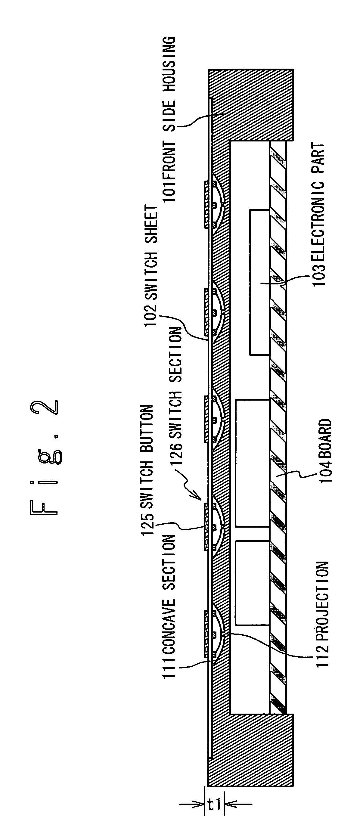
[0033]FIG. 2 is a cross sectional view of the switch integrated type housing according to the first embodiment of the present invention. As shown in FIG. 2, the switch integrated type housing of the present invention has a box-shaped housing body 101 and a switch sheet 102. A plurality of concave sections 111 are formed on the surface of the housing body 101, and a projection 112 is formed in the central portion of the concave section 111. The switch sheet 102 is provided to cover a concave section and at least a part of an outer surface of the housing body other than the concave sections and is fixed to the housing body 111 in the outer surface of the housing body other than the concave sections. Also, a switch button 125 is arranged on the surface portion of the switch sheet 102 corresponding to the concave section. A switch section 126 is formed in the concave section 111 to have a switch button 125. A printed circuit board 104 is arranged inside the housing body 101, and on the ...

second embodiment

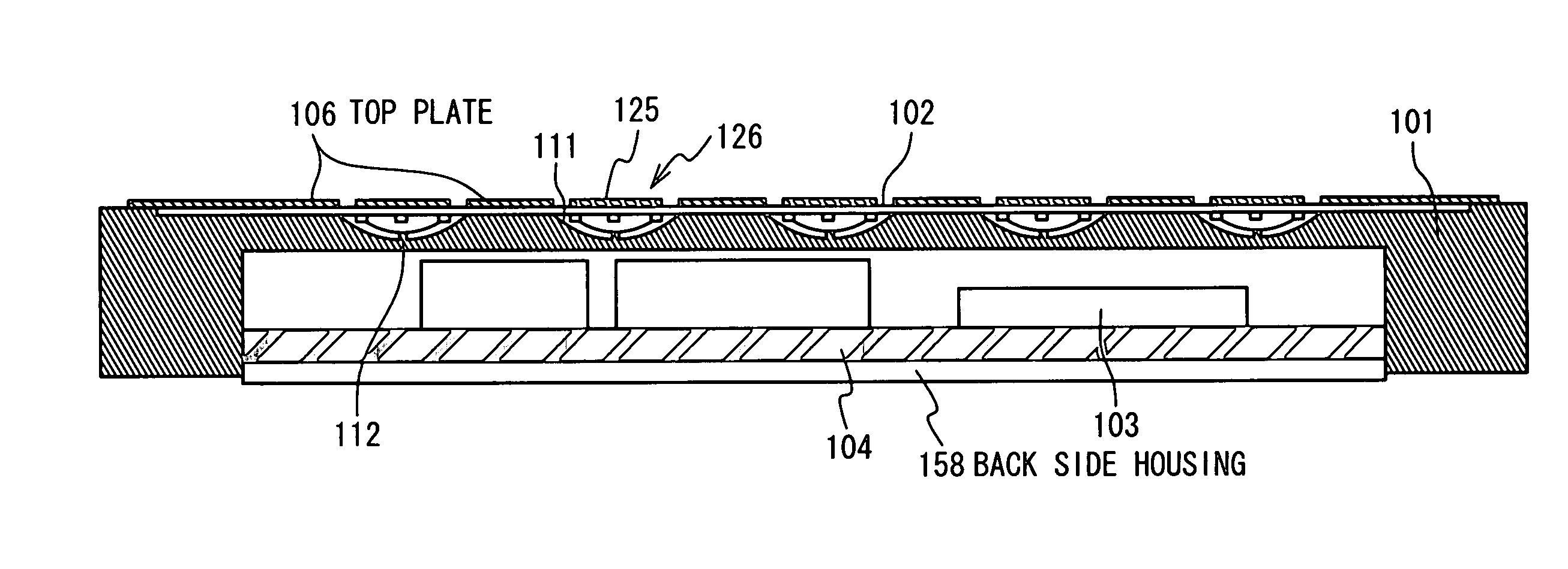
[0040]FIG. 4 is a cross sectional view of the switch integrated type housing according to the second embodiment of the present invention. FIG. 5 is an expanded view of the switch section of FIG. 4. FIG. 6 is a plan view of the switch integrated type housing along the A—A line of FIG. 5. In FIGS. 4, 5, and 6, the same reference numerals are given to the same components of FIGS. 2 and 3, and the description will be appropriately omitted. The second embodiment is different from the first embodiment shown in FIGS. 2 and 3 in the point that an arc section is formed on the switch sheet 102 coaxially with the wiring line patterns 122A and 122B outside the wiring line pattern 122A, and a blanked section 127 is formed to have the arc section and lines extending in parallel from ends of the arc section, and the point that a top plate 106 which has a through-hole in the position corresponding to the switch button 125 is adhered and fixed to the surface of the switch button sheet 102A. The top ...

third embodiment

[0045]FIG. 9 is a cross sectional view of the switch section of the switch integrated type housing according to the third embodiment of the present invention. In FIG. 9, reference numerals similar to those of FIG. 5 are given to the same components of FIG. 5 and the description will be appropriately omitted. The third embodiment is different from the second embodiment shown in FIG. 5 is in the point that any wiring line pattern is not formed on the switch button sheets 202A, two electrodes are formed in the concave section to penetrate the housing body, and openings are provided for portions of the cover sheet opposite to two electrodes. Here, one electrode 222A of the two electrodes is formed to pass through the housing body 201 in the center of the concave section and the top section of the electrode 222A is formed as a projection 212. The other electrode (wiring line pattern) 222B is formed in the neighborhood of the electrode (wiring line pattern) 222A.

[0046]A conductor 224 is f...


PUM


Abstract

A switch integrated type housing includes a housing body, a switch button sheet, a conductor and a cover sheet. The housing body is provided with a plurality of concave sections on an outer surface of the housing body. The switch button sheet is provided on the outer surface to cover the plurality of concave sections. The conductor has a dome shape downwardly projecting and is provided in each of the plurality of concave sections to contact the switch button sheet. The cover sheet is provided between the switch button sheet and the outer surface of the housing body in a portion of the outer surface of the housing body other than the plurality of concave sections and to cover a lower surface of the conductor in each of the plurality of concave sections.

Description

TECHNICAL FIELD[0001]The present invention relates to a housing structure for accommodating a functional section and an electronic equipment using the same.BACKGROUND ART[0002]In a small mobile terminal such as mobile phone, a PHS (Personal Handy Phone System), and a PDA (Personal Digital Assistant), tendency of a small size and a thin structure is accelerating. For the purpose of realization of a small mobile terminal with the small size and thin structure, the small size and thin structure of a functional part, the thin structure of a printed circuit board on which the functional parts are mounted, the small size of an antenna, and the thin structure of a housing which accommodates the functional parts and the printed circuit board and so on are carried forward.[0003]FIG. 1 is a cross sectional view of a conventional small mobile terminal. As shown in FIG. 1, in the conventional small mobile terminal, generally, a front housing 501, switch buttons 525, a key sheet 502, switch dome...

Claims


Application Information

Patent Timeline
Patent Type & Authority Patents(United States)
IPC IPC(8): H01H13/715H01H13/04H05K5/02H01H13/48H01H13/70H01H13/702
CPCH01H13/7006H01H13/702H01H2203/03H01H2203/038H01H2223/003H01H2205/026H01H2215/02H01H2221/002H01H2205/024H01H13/04
Inventor KOBAYASHI, YOSHIAKIYOSHIHIRO, TAKAAKIMIKAMI, NOBUHIRO
Owner LENOVO INNOVATIONS LTD HONG KONG
Why Eureka
Try Eureka