System for profiling objects on terrain forward and below an aircraft utilizing a cross-track laser altimeter

a laser altimeter and forward and downward technology, applied in the field of avionic systems, can solve the problems of difficult to achieve precise measurements of altitude with such systems, inability to provide accurate information above ground level (agl), and inability to provide other information for augmented systems

Inactive Publication Date: 2006-08-22
ROSEMOUNT AEROSPACE
View PDF12 Cites 47 Cited by
  • Summary
  • Abstract
  • Description
  • Claims
  • Application Information

AI Technical Summary

Benefits of technology

[0010]In accordance with another aspect of the present invention, a laser-based system disposed on-board an aircraft for profiling objects on the terrain forward of the aircraft during flight for use in the guidance and control of the aircraft comprises: a forward looking cross track laser altimeter operative to emit pulsed laser beams at a predetermined rate along line swept paths forward and downward at a predetermined angle to the flight path of the aircraft, the pulsed laser beams being line swept back and forth across a ground track forward the aircraft and as the aircraft moves along its flight path, the line sweeps serpentining an area of terrain forward the aircraft, the laser altimeter for receiving returns of the pulsed laser beams from the terrain and objects on the terrain in the area forward the aircraft; the laser altimeter operative to measure times-of-flight and line sweep positions of the returns and generate for each return a data profile comprising range and line sweep position th...

Problems solved by technology

However, precise measurements of altitude are often difficult to achieve with such systems, especially for applications in which precise placement above ground is needed.
Although a GPS has the ability to determine altitude of the aircraft, without a differential GPS receiver, precision above ground level (AGL) information is not possible due to the approximations in the GPS altitude estimation and the particular geodetic datum used.
However, such an augmented system does not provide for other information, such as the presence of trees and other ground objects, for example, which is critical for avoiding collisions during hover and NOE flight conditions.
However, this technique does not account for ground features such as buildings, power lines, and other ground objects resulting in separation differenc...

Method used


Image

  • System for profiling objects on terrain forward and below an aircraft utilizing a cross-track laser altimeter
  • System for profiling objects on terrain forward and below an aircraft utilizing a cross-track laser altimeter
  • System for profiling objects on terrain forward and below an aircraft utilizing a cross-track laser altimeter

Examples


Embodiment Construction

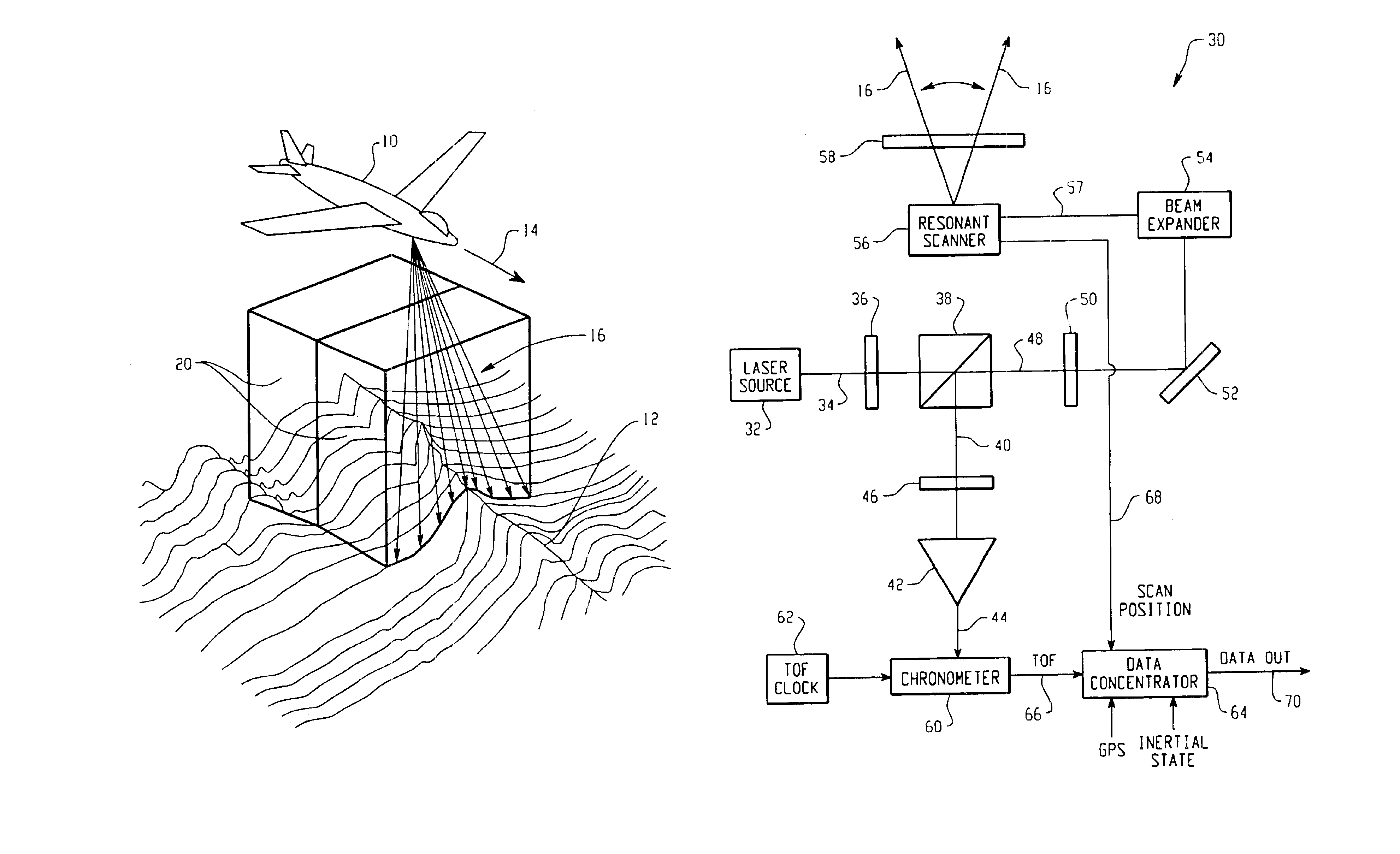
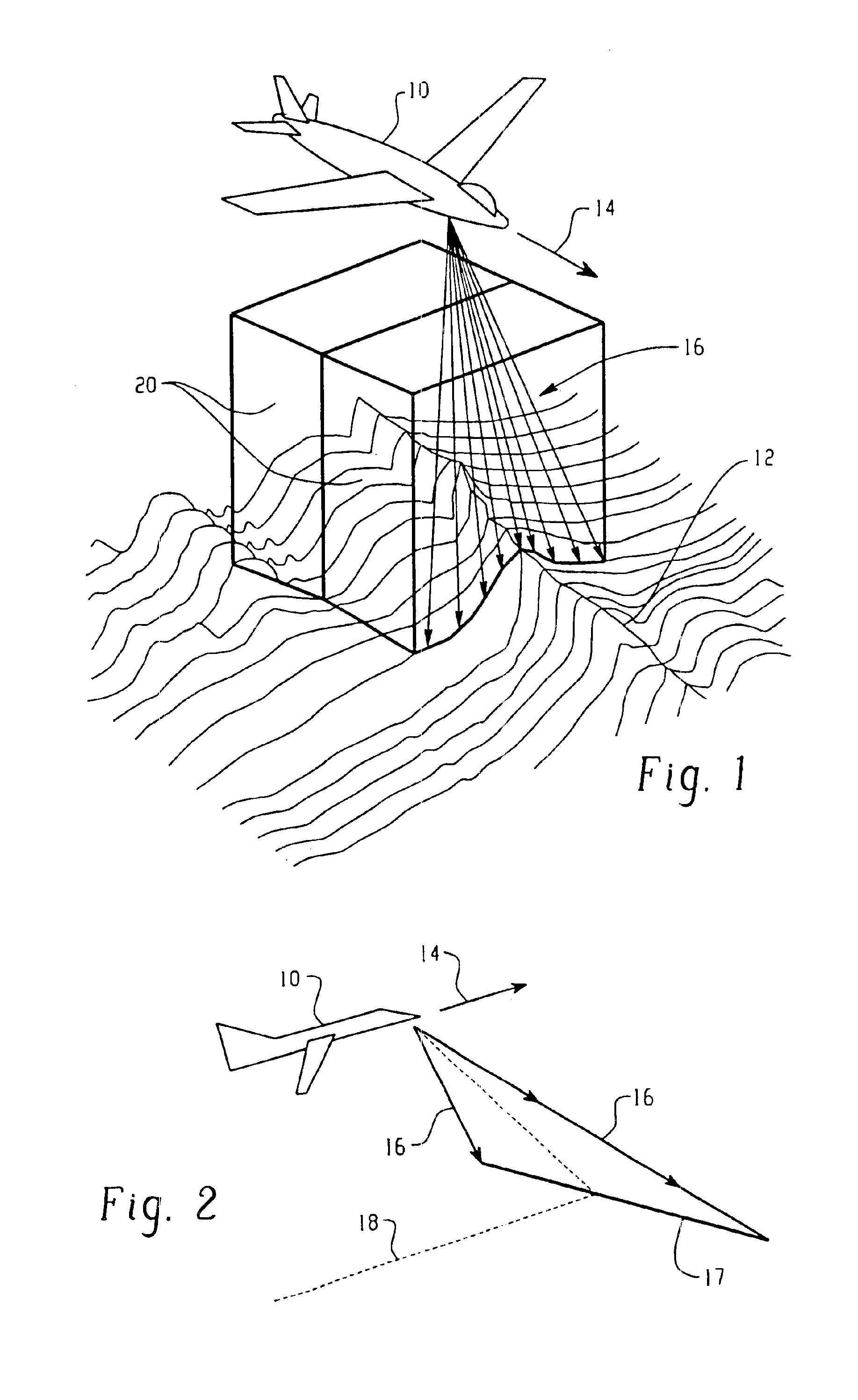
[0020]FIG. 1 is an illustration of an aircraft 10, which may be an UAV, for example, on-board which a cross-track laser altimeter (not shown) is disposed. In FIG. 1, the aircraft 10 is shown flying over terrain 12 which may include ground objects projecting above the ground level in the flight path designated by the arrowed line 14. The on-board laser altimeter transmits pulsed laser beams on the order of 2 milliradians, for example, designated by the arrowed lines 16, from the aircraft 10 towards the ground or terrain 12. As will become more evident from the following description, the laser altimeter scans the pulsed laser beams 16 back and forth across a path 17 substantially perpendicular to the ground track 18 of the aircraft which is shown more clearly in the simple sketch of FIG. 2. This scanning is known as cross-track scanning, which results in the name cross-track laser altimeter. The laser altimeter uses a time of flight technique in a real time environment for gathering A...


PUM


Abstract

A forward looking cross-track laser altimeter comprises: a first configuration of optical elements for guiding pulsed laser beams along a first optical path; a mirror element coupled to a scanner and disposed in the first optical path, the scanner operative to oscillate the mirror element to sweep the reflected laser beams back and forth across a line at a predetermined frequency; the scanner and mirror element configurable to reflect the pulsed laser beams along paths forward and downward at a predetermined angle to the flight path of the aircraft, wherein the pulsed laser beam paths are caused to be line swept across a ground track forward the aircraft; the mirror element for receiving returns of the pulsed laser beams from the terrain and objects on the terrain forward the aircraft and reflecting the returns along a second optical path to a light detector which produces a return signal in response thereto; a first circuit governed by the return signals for measuring times-of-flight of the returns and generating time-of-flight signals corresponding thereto; the scanner for generating a line sweep position signal; and a second circuit for generating for each return a data profile comprising range and line sweep position thereof based on the corresponding time-of-flight and position signals.

Description

BACKGROUND OF THE INVENTION[0001]The present invention is directed to avionic systems for measuring height above ground level for terrain avoidance during flight and landing in general, and more particularly, to a system for profiling objects on the terrain forward and below the aircraft utilizing a cross-track laser altimeter to avoid collision therewith during flight and landing.[0002]Today's military and commercial aircraft desire more precise measurements of aircraft position and position information. Ground based RADAR systems and Global Positioning Systems (GPS) allow for precise positioning of an aircraft in latitude and longitude desirable for air traffic control, aircraft separation, and navigation. However, precise measurements of altitude are often difficult to achieve with such systems, especially for applications in which precise placement above ground is needed. New levels of precision for altitude measurements, on the order of + / −6 inches (15 cm), for example, are oft...

Claims


Application Information

Patent Timeline
IPC IPC(8): G01C3/08G01B11/26G01C1/00G01S7/481G01S7/483G01S7/499G01S17/42G01S17/89G01S17/933
CPCG01S7/4811G01S7/4817G01S7/483G01S17/933G01S17/42G01S17/89G01S7/499
Inventor JAMIESON, JAMES R.RAY, MARK D.PESIK, JOSEPH T.
Owner ROSEMOUNT AEROSPACE
Why Eureka
Try Eureka