Communication method and apparatus for a radio local area network system using macrodiversity

macrodiversity technology, applied in the field of communication methods and apparatus for a radio local area network (lan) system, can solve the problems of radio transmission path interruption between the transmitting unit and the receiving unit, and achieve the effects of low transmit power, low antenna gain, and narrow transmission frequency band

Inactive Publication Date: 2006-08-22
FUJITSU LTD
View PDF27 Cites 3 Cited by
  • Summary
  • Abstract
  • Description
  • Claims
  • Application Information

AI Technical Summary

Benefits of technology

[0011]It is an object of the present invention to provide a communication method and apparatus for a radio LAN system using a macrodiversity function. In the method and apparatus, a broad band transmission may be provided with relatively low transmit power, relatively low antenna gain, and a relatively narrower transmission frequency band. This permits the disadvantages described above to be eliminated.

Problems solved by technology

However, for example, in a radio LAN system used in an office, a radio transmission path between the transmit unit and the receive unit may be interrupted by person's motion or movement of people.
However, the following problem occurs in the above-discussed prior-art radio LAN system.

Method used


Image

  • Communication method and apparatus for a radio local area network system using macrodiversity
  • Communication method and apparatus for a radio local area network system using macrodiversity
  • Communication method and apparatus for a radio local area network system using macrodiversity

Examples


first embodiment

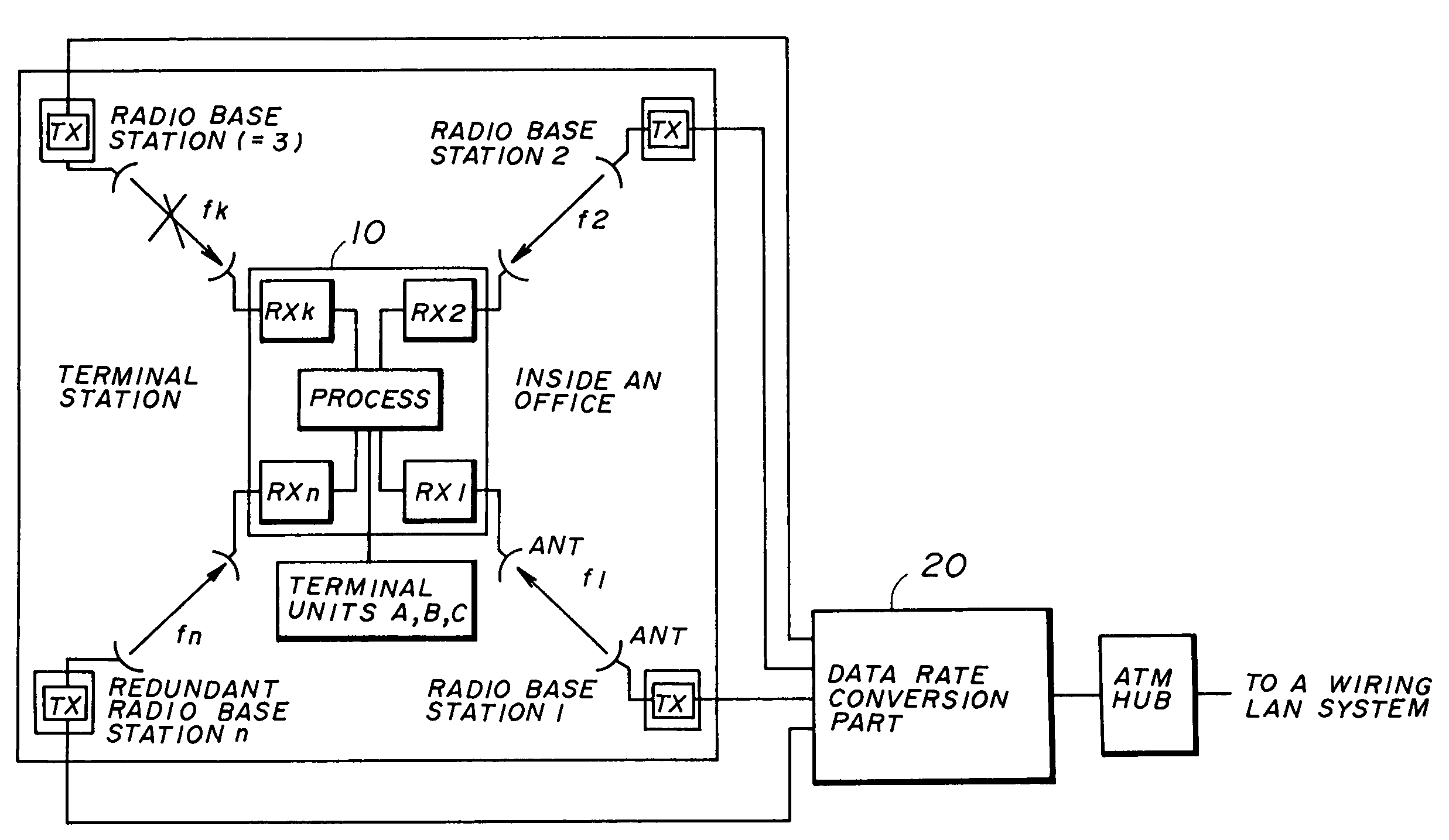
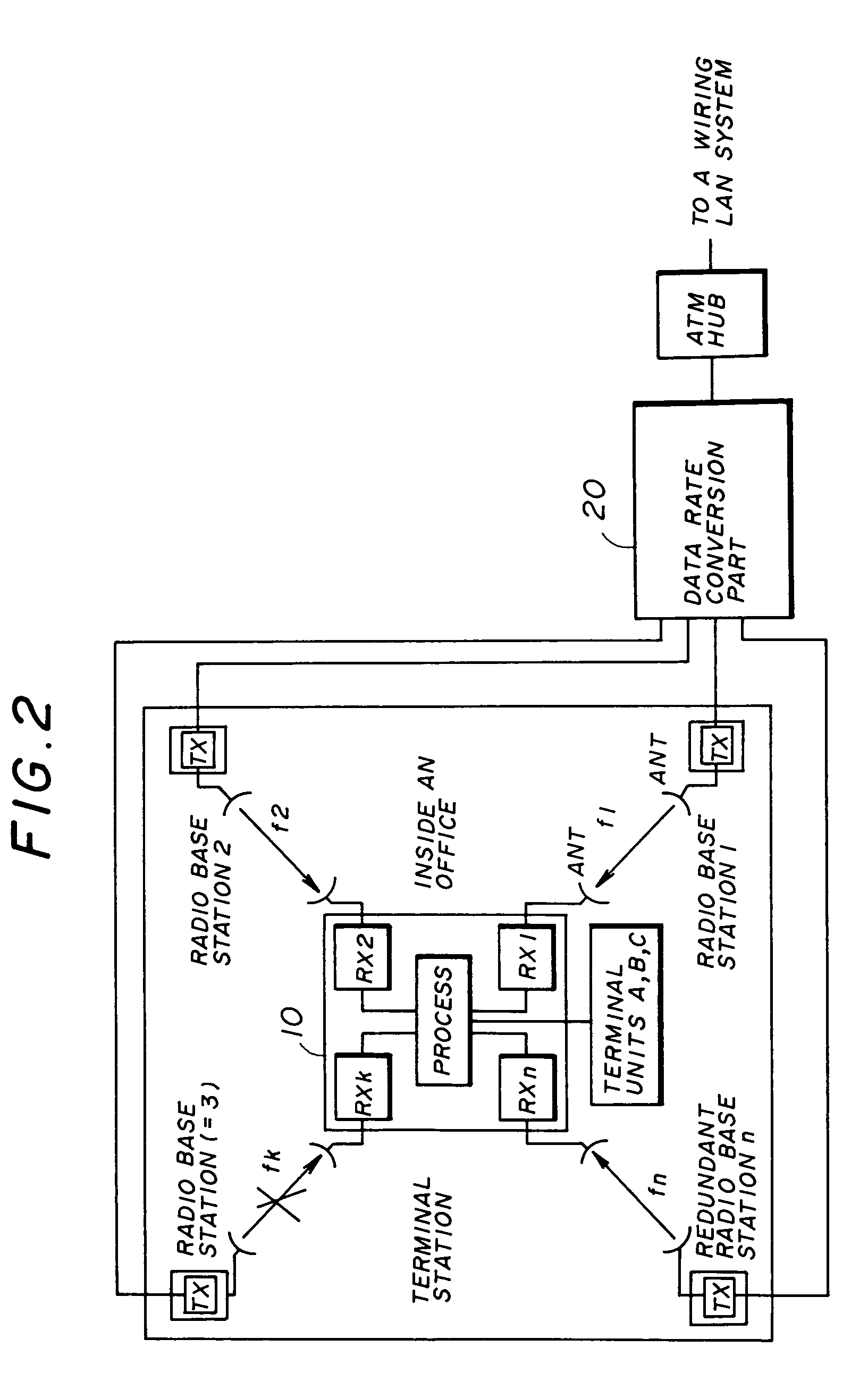
[0047]In the first embodiment shown in FIG. 2, the radio base station n is used for the redundant radio base station (discussed in detail later). A signal transmitted from an external wiring LAN system is provided to a data-rate conversion part 20 through a HUB in an ATM. This input signal is represented by the signal A shown in FIG. 3. The input signal contains a signal for a terminal unit A, a signal for a terminal unit B, and a signal for a terminal unit C in addition to a discrimination signal.

[0048]Different cases can exist in a connecting relation between the terminal station 10 and the terminal units A to C. For example, in one case, for each terminal station, the terminal unit is provided. In another case, a plurality of terminal units belong to a single terminal station. In either cases, by an address provided for each data, each data may be properly transmitted to an addressed terminal unit.

[0049]In the data-rate conversion part 20, as shown in the signals B in FIG. 3, the...

second embodiment

[0068]Namely, in the second embodiment shown in FIG. 7, in the same way as the data-rate conversion part 20 shown in FIG. 2, in a data-rate conversion part 40, the signal (for example, 156 Mbps) transmitted from the wiring LAN system through the ATM-HUB is distributed into (n−1) signals corresponding to the radio base stations 1 to n−1. Further, the distributed signals are converted to lower-rate signals (for example, 156 / (n−1) Mbps). The above-discussed operation is carried out in a rate-conversion-and-distribution circuit 42 shown in FIG. 8.

[0069]Further, in the data-rate conversion part 40 shown in FIG. 8, the signals for the (n−1) conventional radio base stations are distributed into two groups of signals (for example, odd-number radio base stations and even-number radio base stations). In summation circuits 44-1, 44-2, the two groups of signals are respectively summed for each given timeslot to generate two signals for the redundant radio base station n and the redundant radio ...

third embodiment

[0080]In the radio LAN system according to the present invention shown in FIG. 10, inside the office, for the single terminal station 50 connected to at least one terminal unit, a plurality of radio base stations (in this case, radio base stations 1 to n) are provided. In the third embodiment shown in FIG. 10, the radio base station n is used for the redundant radio base station. Further, between the respective radio base stations and the terminal station 50, two-way communications are established. Therefore, as shown in FIG. 11, in each radio base station (including a data-rate conversion part 60) and the terminal station 50, a transmitter, the rate-conversion-and-distribution circuit, and the rate-conversion-and-multiplex circuit are respectively provided.

[0081]Further, because of the two-way communication, by monitoring an up-link transmission path from the terminal station 50 to the radio base station, the radio base station also may monitor whether the transmission path is inte...


PUM


Abstract

A communication method for a radio LAN system provides communication at a first transmission rate. In the method, a first signal of the first transmission rate is time-divisionally distributed into n−1 second signals (n=3, 4, . . . ). The n−1 second signals are respectively converted into n−1 third signals of a second transmission rate less than the first transmission rate. The n−1 third signals of the second transmission rate are also transmitted through radio transmission paths between n−1 radio base stations and a terminal station connected to at least one terminal unit.

Description

BACKGROUND OF THE INVENTION[0001]1. Field of the Invention[0002]The present invention generally relates to a communication method and apparatus for a radio local area network (LAN) system, and more particularly, to a communication method and apparatus for a radio local area network (LAN) system, in which transmission performance may be improved by macrodiversity using a plurality of radio base stations.[0003]2. Description of the Related Art[0004]Recently, in a radio LAN system using a millimeter-wave band (for example, 30 GHz to 60 GHz), a very broad band transmission (for example, more than 100-Mbps bit rate) is developing. In this case, taking millimeter-wave transmission performance into account, communication between a transmit unit and a receive unit needs to be a line-of-sight communication.[0005]However, for example, in a radio LAN system used in an office, a radio transmission path between the transmit unit and the receive unit may be interrupted by person's motion or movem...

Claims


Application Information

Patent Timeline
Patent Type & Authority Patents(United States)
IPC IPC(8): H04J3/14H04B7/02H04B7/005H04L12/28
CPCH04B7/022H04W4/18H04W28/22H04W88/181H04W84/12H04W88/08H04W52/40
Inventor ARAI, KOJI
Owner FUJITSU LTD
Why Eureka
Try Eureka