Backhaul multicasting using Ethernet-based radio access networks

a radio access network and backhaul technology, applied in the field of wireless communications networks, can solve the problems of inefficiency and multicast feature, and achieve the effect of improving downlink backhaul services, facilitating multicast traffic transmission, and facilitating faster and smoother handoffs

Inactive Publication Date: 2006-08-22
LUCENT TECH INC
View PDF19 Cites 26 Cited by
  • Summary
  • Abstract
  • Description
  • Claims
  • Application Information

AI Technical Summary

Benefits of technology

[0007]The present invention sets forth a methodology for providing improved downlink backhaul services from a radio network controller (RNC) to a plurality of base stations via a backhaul network that provides Ethernet services. The Ethernet services are provided by a group of provider edge (PE) switches and regular label switch routers (referred to as P switches). Base stations within the network are assigned into clusters, each of the clusters having a cluster ID. The RNC transmits packets to a given switch or switches out on the network based on a cluster ID included within the transmitted packet. The communications traffic is then multicast from at least one last hop switch in the network to candidate base stations on the basis of the cluster ID and an active set within the cluster. Advantageously, the clusters act as subgroups for more easily directing the transmission of the backhaul multicast traffic. Significant advantages are realized through use of the present invention, including the ability to allow faster and smoother handoffs, as well as backhaul bandwidth savings since intelligence regarding cell switching is extended out at a point farther along the network than was previously enabled.

Problems solved by technology

Without a native layer2 multicast service, however, one has to resort to higher layers, such as Layer 3 IPMulticast, to provide such a multicast feature, which is not as efficient.

Method used


Image

  • Backhaul multicasting using Ethernet-based radio access networks
  • Backhaul multicasting using Ethernet-based radio access networks
  • Backhaul multicasting using Ethernet-based radio access networks

Examples


Embodiment Construction

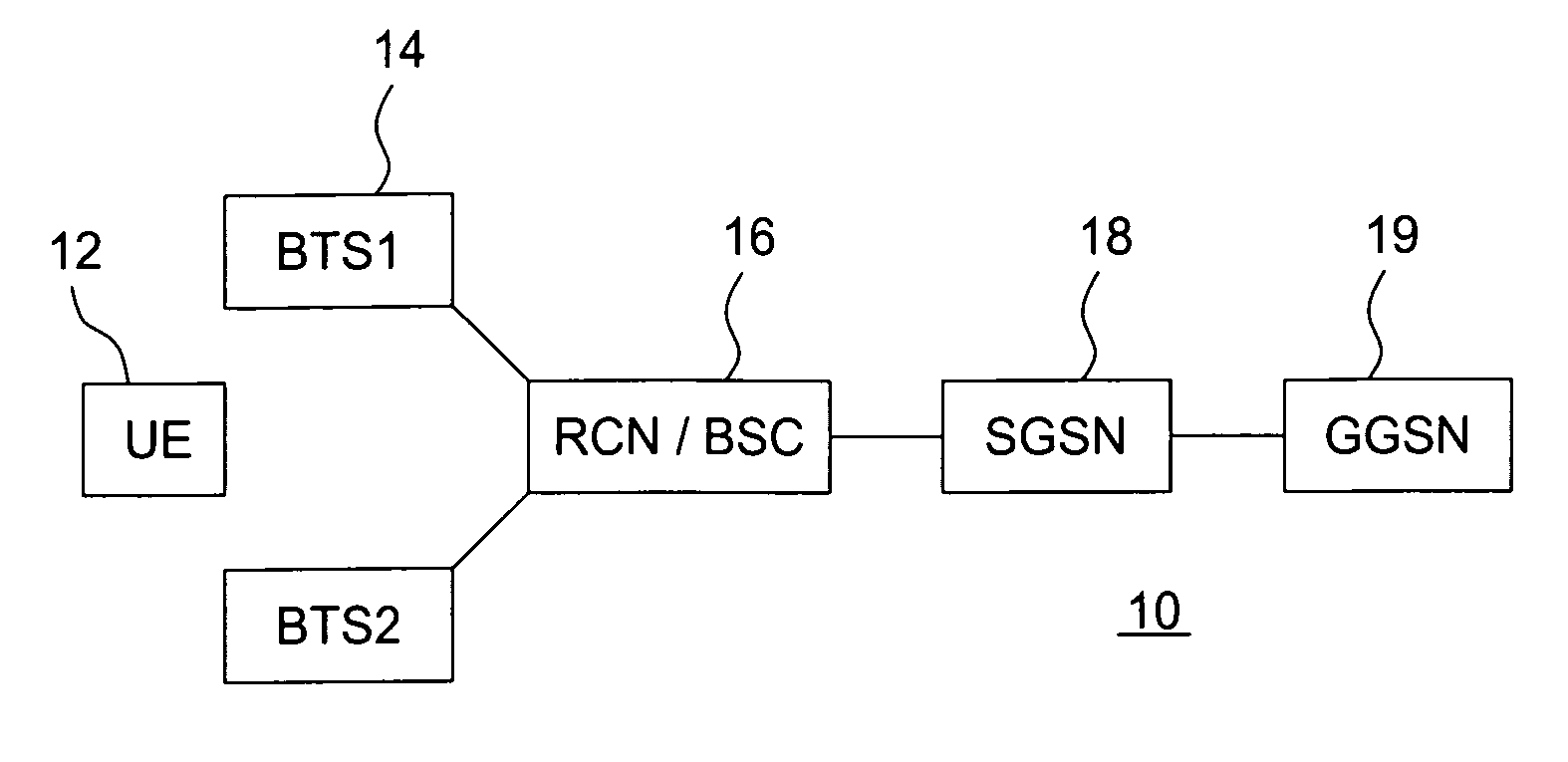
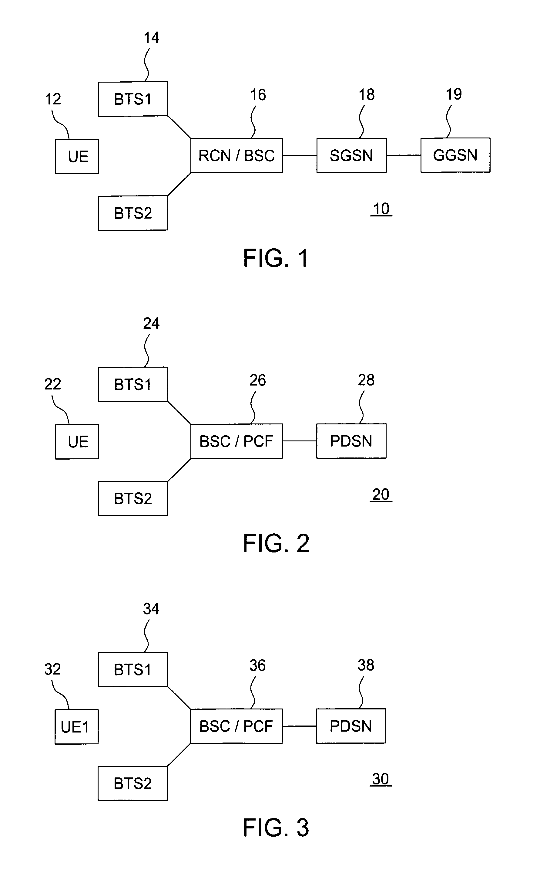
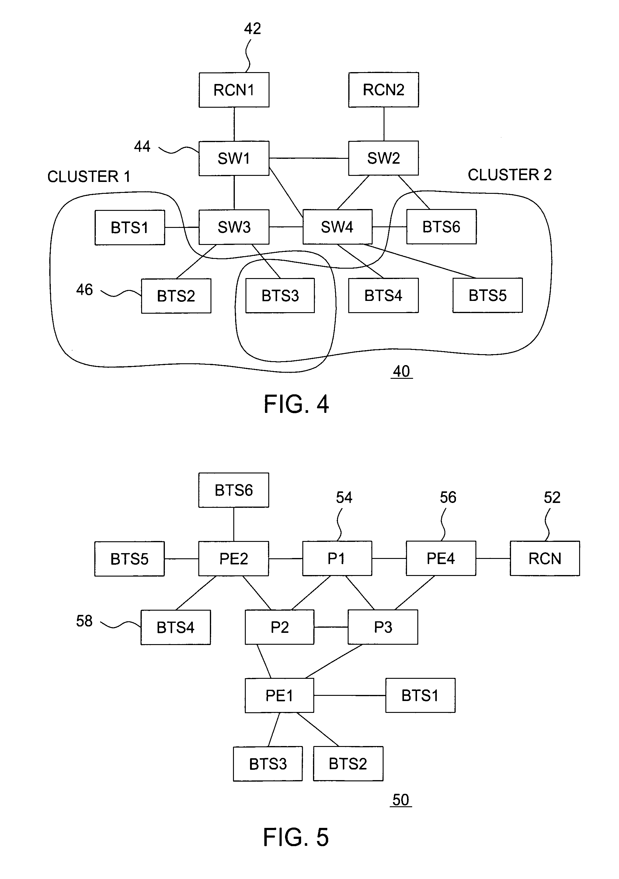
[0016]The present invention sets forth the use of layer 2 Ethernet multicast services for use in a new backhaul solution for a radio access network, e.g., HDR or 4G wireless networks. With the availability of layer 2 Ethernet multicast services, backhaul transmissions can be simplified. It should be noted that this multicast feature is intended to support communications between the BTSs (base transmitting stations) and the BSC (base station controllers) as part of the backhaul network infrastructure, and is not intended to be used to support IP multicast between UE and other hosts. Also, although the invention is described with respect to HDR systems, it would be understood that the principles of the present invention are equally applicable to other wireless technologies, including for example HSDPA (a 3 GPP UMTS Release 5 feature) [TR25.855], 3G1x and UMTS [TR23.1011].

[0017]A first aspect of the present invention, is that the base stations (BTSs) of a network employing the inventio...


PUM


Abstract

The present invention sets forth a methodology for providing improved downlink backhaul services from a radio network controller (RNC) to a plurality of base stations via a backhaul network that provides Ethernet services. The Ethernet services are provided by a group of provider edge (PE) switches and regular label switch routers (referred to as P switches). Base stations within the network are assigned into clusters, each of the clusters having a cluster ID. The RNC transmits packets to a given switch or switches out on the network based on a cluster ID included within the transmitted packet. The communications traffic is then multicast from at least one last hop switch in the network to candidate base stations on the basis of the cluster ID and an active set within the cluster. Advantageously, the clusters act as subgroups for more easily directing the transmission of the backhaul multicast traffic. Significant advantages are realized through use of the present invention, including the ability to allow faster and smoother handoffs, as well as backhaul bandwidth savings since intelligence regarding cell switching is extended out at a point farther along the network than was previously enabled.

Description

FIELD OF THE INVENTION[0001]The present invention relates generally to wireless communications networks and, more particularly, to Fourth Generation (4G) radio access networks.BACKGROUND OF THE INVENTION[0002]Referring to FIGS. 1, 2 and 3, there are shown exemplary block diagrams of radio access networks for three different wireless technologies. FIG. 1 shows a UMTS (universal mobile telephone system) network 10 where user equipment 12, depending on location, wirelessly communicates with one of two base transmitting stations 14. The base stations, in turn, communicate with a radio network controller / base station controller (RNC / BSC) 16. The RNC / BSC communicates with a serving GPRS support node (SGSN) 18 which communicates to a gateway GPRS support node (GGSN) 19. FIG. 2 shows a CDMA 2000 (also referred to as 3G1X) network 20 where user equipment 22 communicates with either a first or second base station 24. The base stations communicate with a base station controller / packet control ...

Claims


Application Information

Patent Timeline
Patent Type & Authority Patents(United States)
IPC IPC(8): H04M1/00H04L12/18H04L12/56H04W92/12
CPCH04L12/189H04L49/201H04L12/1836H04W92/12H04L49/205H04L49/351
Inventor CHUAH, MOOI CHOOHERNANDEZ-VALENCIA, ENRIQUELAU, WING CHEONG
Owner LUCENT TECH INC
Why Eureka
Try Eureka