Tracking the least frequently erased blocks in non-volatile memory systems

a non-volatile memory system and block technology, applied in the field of mass digital data storage systems, can solve the problems of loss of use, significant performance degradation, adverse effects on users of flash memory systems, etc., and achieve the effect of facilitating the allocation of less worn blocks

Inactive Publication Date: 2006-08-22
SANDISK TECH LLC
View PDF41 Cites 165 Cited by
  • Summary
  • Abstract
  • Description
  • Claims
  • Application Information

AI Technical Summary

Benefits of technology

[0016]By maintaining worn elements, e.g., extended blocks, of a non-volatile memory in a group of worn elements, the wear of the worn elements may be managed essentially by preventing the worn elements from being allocated for use until less worn elements eventually become more worn. As such, the wear of all elements may be evened out, as the elements which have been erased more often are effectively prevented from being used and, hence, erased again, until other elements have been used and erased more. The overall ...

Problems solved by technology

When a block is worn out, thereby causing a loss of use or a significant degradation of performance to a portion of the overall storage volume of the flash memory system, a user of the flash memory system may be adversely affected, as for the example through the loss of stored data or the inability to store data.
However, if a block is repetitively written to and erased, e.g., cycled, the wear associated with that block will generally be relatively high.
When some blocks are effectively worn out while other blocks are relatively unworn, the existence of the worn out blocks generally compromises the overall performance of the flash memory system.
In addition to degradation of performance associated with worn out blocks themselves, the overall performance of the flash memory system may be compromised when an insufficient number of blocks which are not worn out are available to store desired data.
Often, a flash memory system may be deemed unusable when a critical number worn out blocks are ...

Method used


Image

  • Tracking the least frequently erased blocks in non-volatile memory systems
  • Tracking the least frequently erased blocks in non-volatile memory systems
  • Tracking the least frequently erased blocks in non-volatile memory systems

Examples


Embodiment Construction

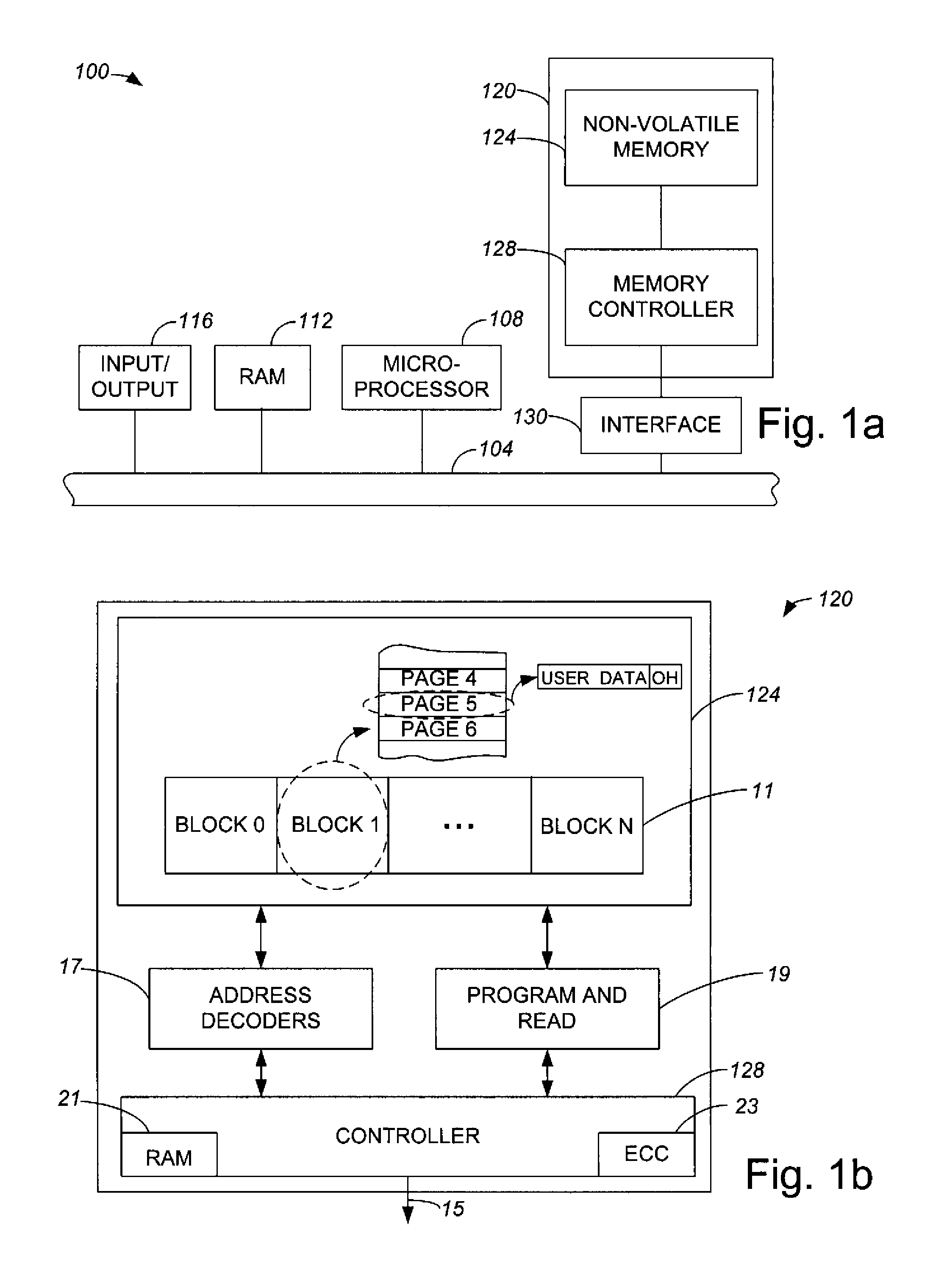
[0031]Non-volatile memory storage blocks within flash memory storage systems may be repetitively programmed and erased, although each block may generally only be erased a finite number of times before the block wears out. When a block wears out, a relatively significant degradation of performance associated with the portion of the overall storage volume of the flash memory storage system that includes the worn out block occurs, and data stored in that portion may be lost, or it may become impossible to store data in that portion.

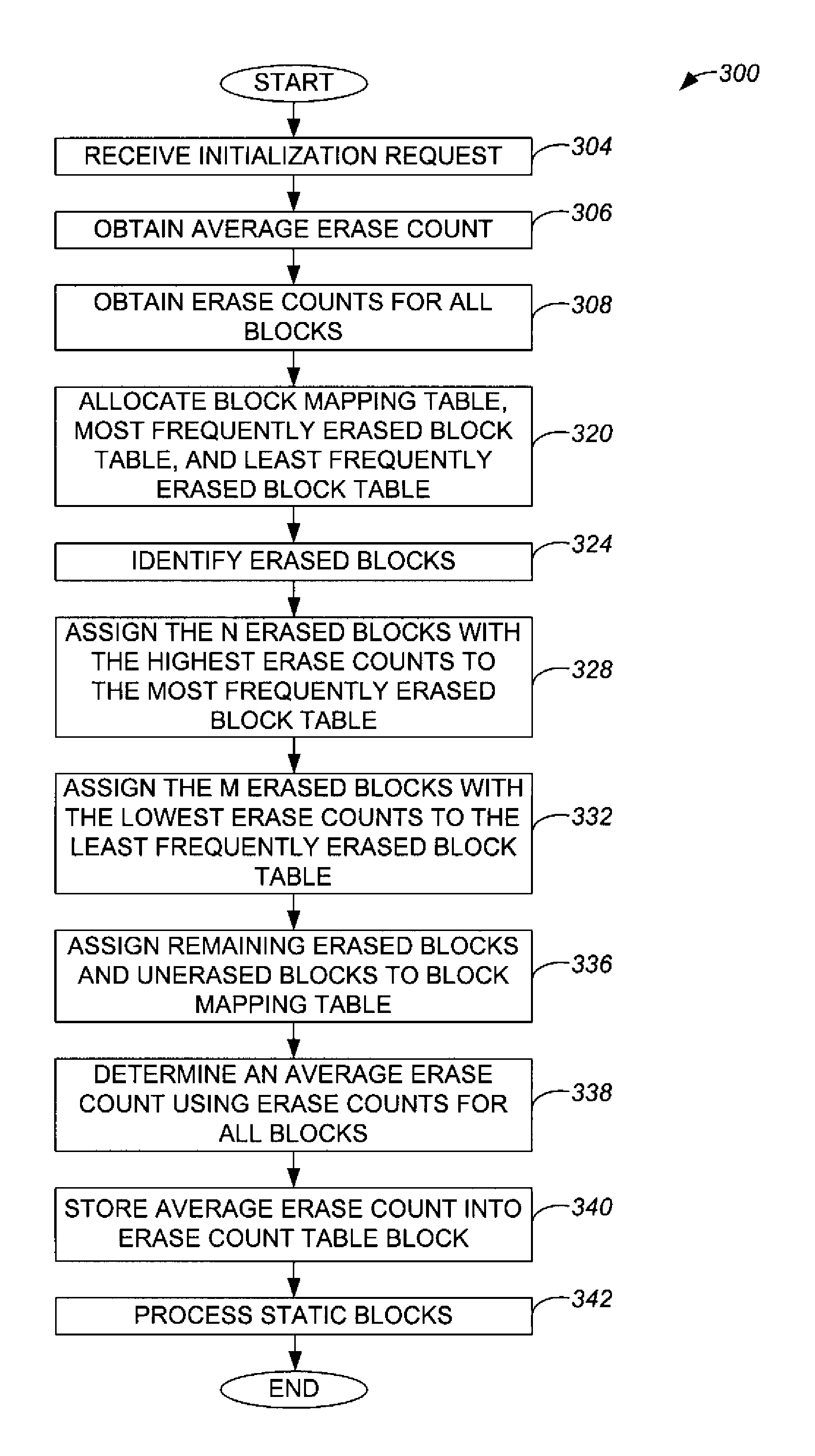
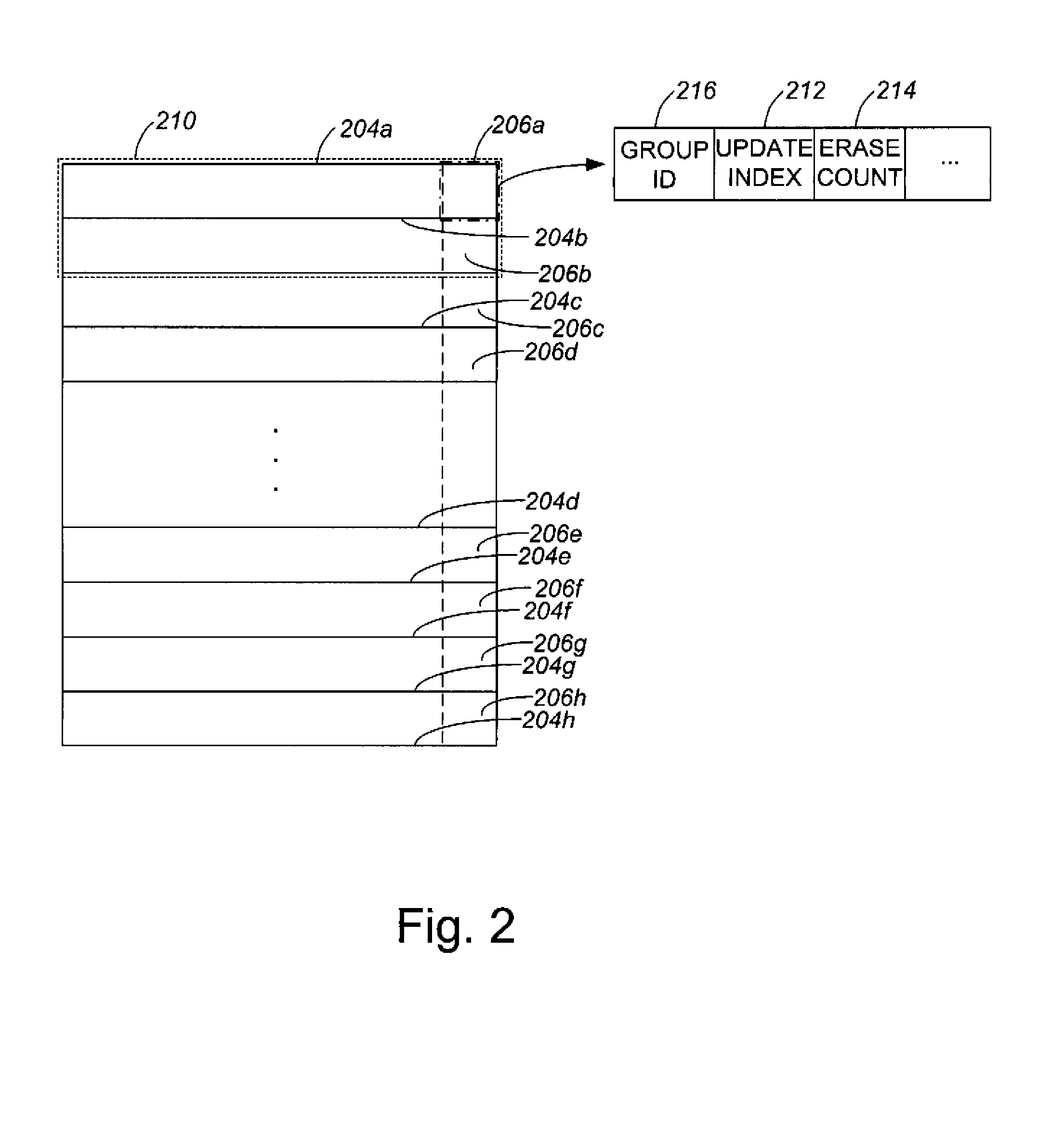
[0032]In order to increase the likelihood that blocks wear out more evenly within a flash memory storage system, blocks may be more evenly utilized. By keeping track of how many times each block has been erased, as for example through the utilization of an erase count, memory within a system may be more evenly used. An erase count management technique may store an erase count which keeps track of how many times a particular block has been erased in a redunda...


PUM


Abstract

Methods and apparatus for performing wear leveling in a non-volatile memory system are disclosed. According to one aspect of the present invention, one method for processing elements included in a non-volatile memory of a memory system includes obtaining erase counts associated with elements and grouping a number of the elements into a first set. Each element has an associated erase count that substantially indicates a number of times the element has been erased. Grouping the number of elements into the first set includes selecting elements included in the plurality of elements which have the lowest associated erase counts of the erase counts associated with the plurality of elements. The method also includes storing the erase counts associated with the first set in a memory component substantially within a table.

Description

CROSS REFERENCE TO RELATED APPLICATIONS[0001]The present invention is related to co-pending U.S. patent application Ser. No. 10 / 281,739 entitled “WEAR-LEVELING IN NON-VOLATILE SYSTEMS”, filed Oct. 28, 2002; co-pending U.S. patent application Ser. No. 10 / 281,670 entitled “TRACKING THE MOST FREQUENTLY ERASED BLOCKS IN NON-VOLATILE MEMORY SYSTEMS,” filed Oct. 28, 2002: co-pending U.S. patent application Ser. No. 10 / 281,631 entitled “METHOD AND APPARATUS FOR SPLITTING A LOGICAL BLOCK”, filed Oct. 28, 2002; co-pending U.S. patent application Ser. No. 10 / 281,855 entitled “METHOD AND APPARATUS FOR GROUPING PAGES WITHIN A BLOCK”, filed Oct. 28, 2002; co-pending U.S. patent application Ser. No. 10 / 281,762 entitled “METHOD AND APPARATUS FOR RESOLVING PHYSICAL BLOCKS ASSOCIATED WITH A COMMON LOGICAL BLOCK,” filed Oct. 28, 2002; which are each incorporated herein by reference in their entireties.BACKGROUND OF THE INVENTION[0002]1. Field of Invention[0003]The present invention relates generally ...

Claims


Application Information

Patent Timeline
IPC IPC(8): G06F12/00G06F12/02
CPCG06F12/0246G06F2212/7211G06F2212/1036G06F12/00G06F12/02
Inventor CHANG, ROBERT C.QAWAMI, BAHMANSABET-SHARGHI, FARSHID
Owner SANDISK TECH LLC
Why Eureka
Try Eureka