

Method of and device for joining assembled hollow shafts
- Summary
- Abstract
- Description
- Claims
- Application Information
AI Technical Summary
Benefits of technology
Problems solved by technology
Method used
Image

Examples
Embodiment Construction
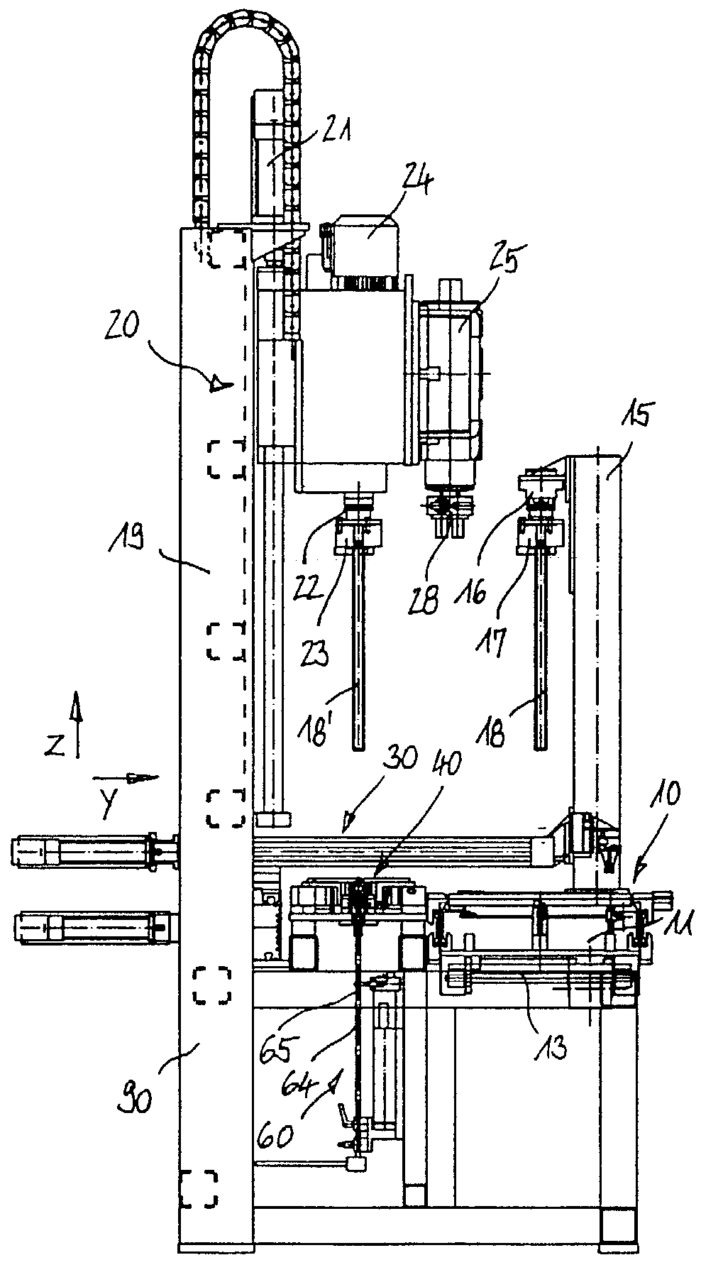
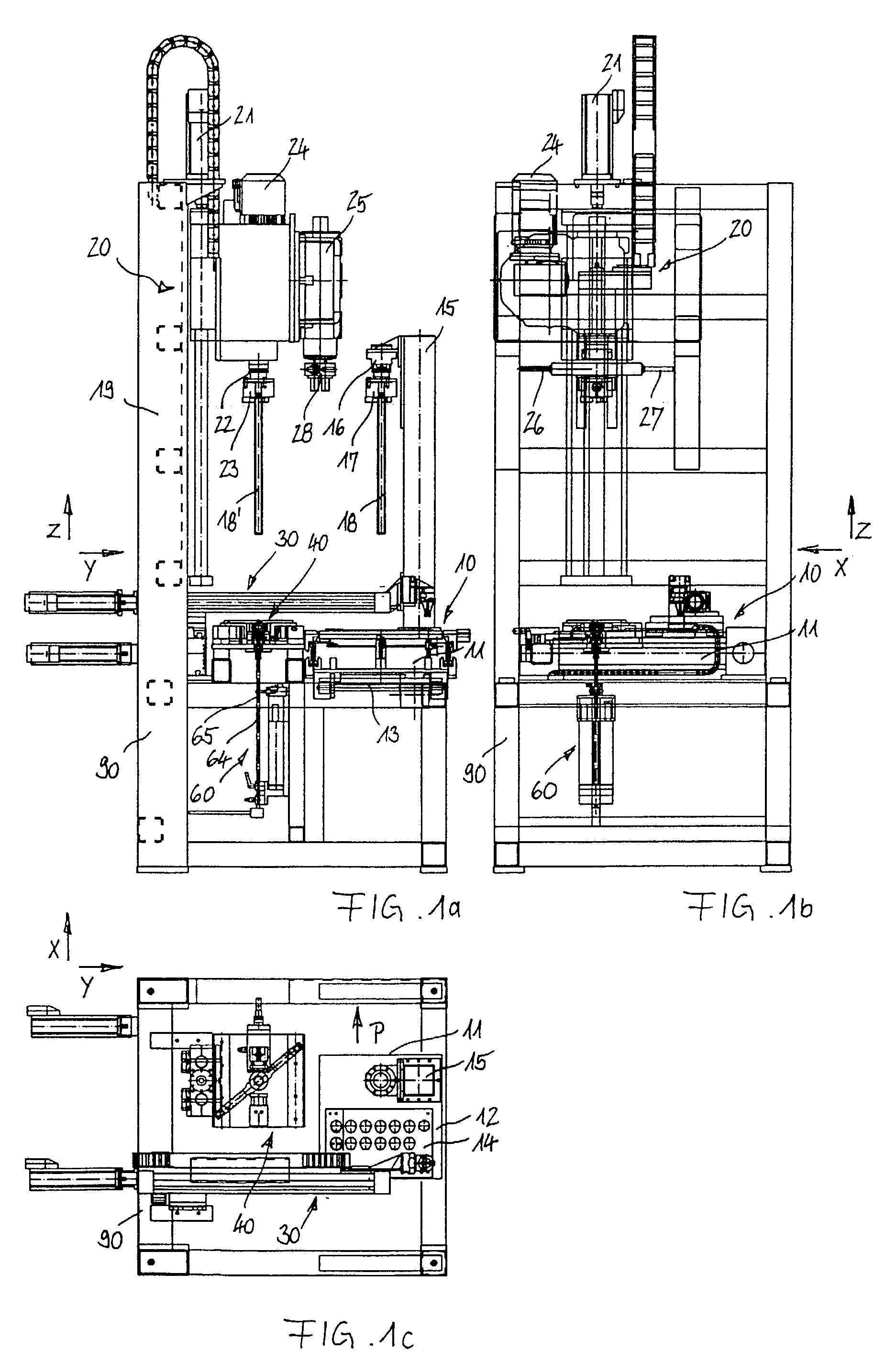
[0042]Below, the three illustrations of the joining station according to FIG. 1 will be described jointly. Three axes of movement have been given the reference symbols x, y, and z. A rack 90 is shown comprising a workpiece transporting unit 10 which is horizontally transportable in the direction of arrow P. The workpiece transporting unit 10 includes a pallet 11 and a stand 15. The pallet workpiece transporting unit 10 runs on a transport track 13 extending inside the device. In particular, it is possible, here, to provide one groove at the pallet 11 at the groove edge extending parallel relative to the direction of movement and two bores at the opposite edge extending parallel relative to the transport direction. The receiving mechanism is loaded from one side by a 90° prism extending parallel relative to the transport direction and, from the other side, by two tapered pins positioned in the same horizontal plane, so that the pallet 11 is fixed in an accurate horizontally aligned p...
PUM
 Abstract
Description
Claims
Application Information