Hollow polymer fiber optic system for single analyte and multiplexed analyte detection

a fiber optic system and polymer fiber technology, applied in the field of analyte detection methods, systems and apparatuses, can solve the problems of inability to carry around existing systems that utilize alpha technology, and systems are typically not very accurate, so as to simplify the detection process, simplify the doping process, and the effect of simple and convenient approach

Active Publication Date: 2020-06-09
PERKINELMER HEALTH SCIENCES INC
View PDF7 Cites 1 Cited by
  • Summary
  • Abstract
  • Description
  • Claims
  • Application Information

AI Technical Summary

Benefits of technology

[0012]In certain embodiments, the system is portable, easy to use, and provides robust measurement (qualitative and / or quantitative) of one or more analytes of interest. In particular, for crop sciences and animal health applications, samples traditionally need to be procured in the field and brought back to the lab for analysis. The hollow polymer fiber optic system described herein provides a robust, easy-to-use, dependable system for making such measurements in the field rather than in the lab. Moreover, very small volumes of sample are sufficient for testing, given the small internal volume of the hollow fiber optic tubes. The hollow tubes also simplify sample procurement, handling, and transport.
[0027]In certain embodiments, the polymer optic fiber comprises a first binding partner (e.g., a first antibody, e.g. streptavidin) bound on an interior surface of the polymer optic fiber. In certain embodiments, the polymer optic fiber comprises multiple discrete portions along its length, each of which portions has a different concentration of the first binding partner conjugated to its interior surface for achieving a variety of levels of sensitivity of measurement of an analyte of interest to which the first binding partner binds. In certain embodiments, the polymer optic fiber comprises multiple discrete portions along its length, each of which has a different binding partner conjugated to its interior surface. In certain embodiments, the different binding partners are different antibodies. In certain embodiments, each binding partner is capable of binding to a different variant of a specific antigen. In certain embodiments, each binding partner is capable of binding to a different analyte.

Problems solved by technology

The existing systems that utilize alpha technology are not portable.
These systems are typically not very accurate, and are usually limited to qualitative analyses.

Method used


Image

  • Hollow polymer fiber optic system for single analyte and multiplexed analyte detection
  • Hollow polymer fiber optic system for single analyte and multiplexed analyte detection
  • Hollow polymer fiber optic system for single analyte and multiplexed analyte detection

Examples


example 3

e Hollow Polymer Optical Fiber for Increasing Binding Surface Area

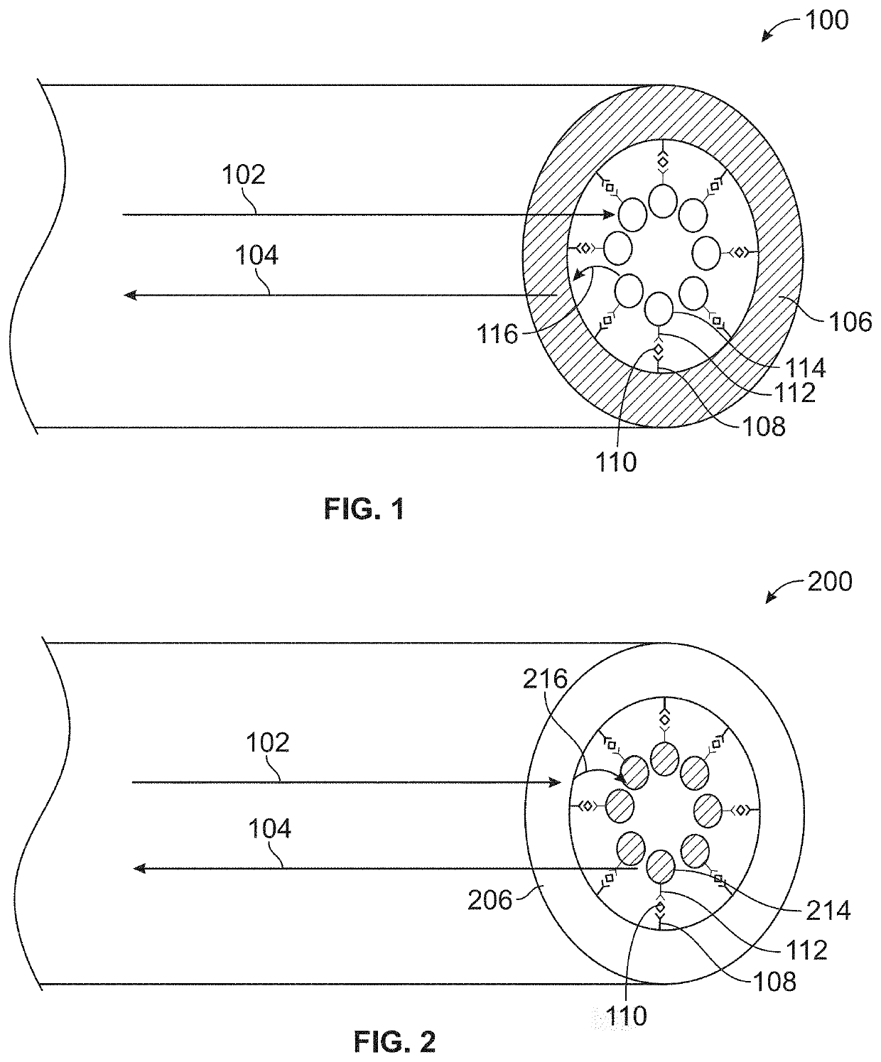
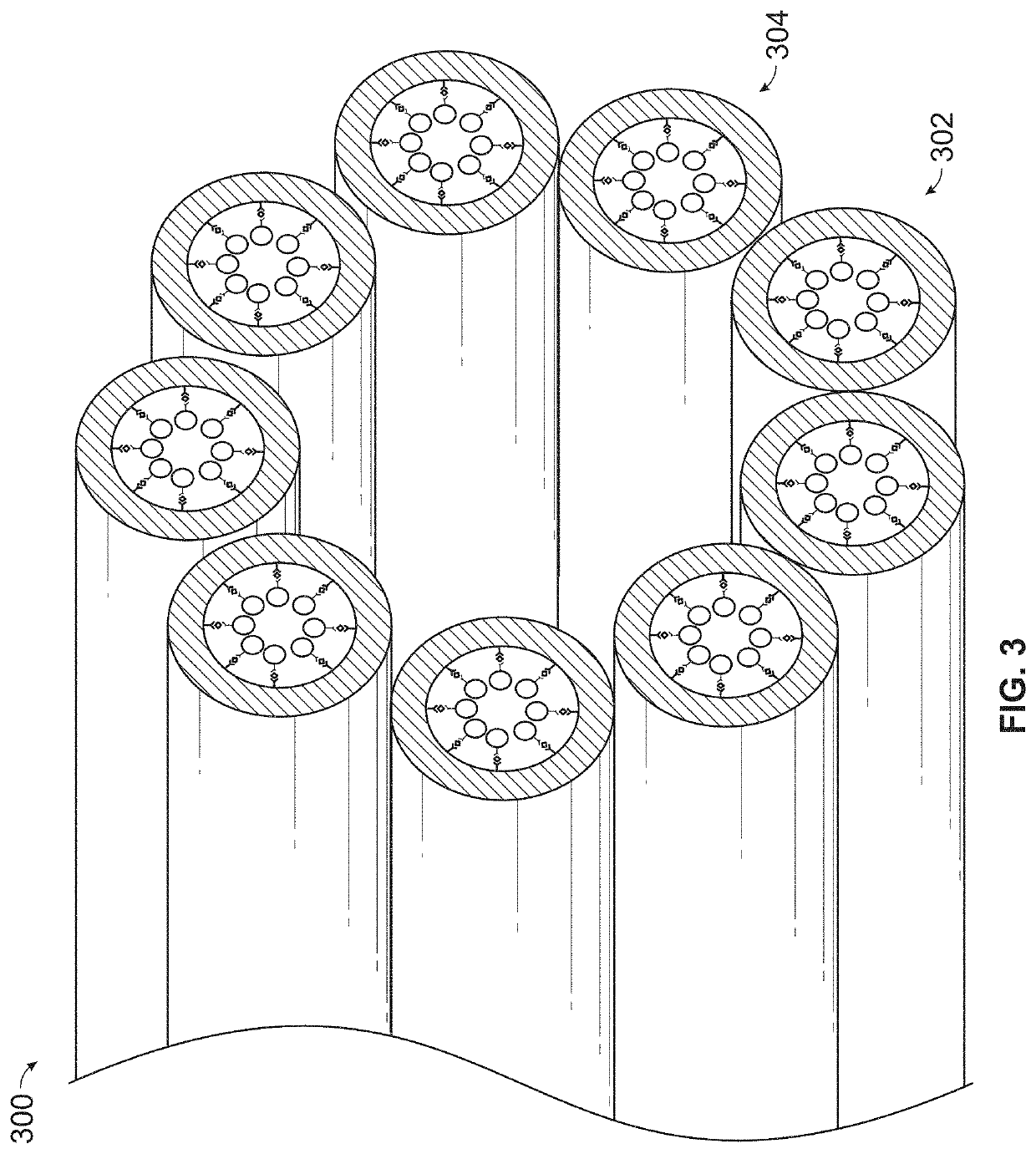
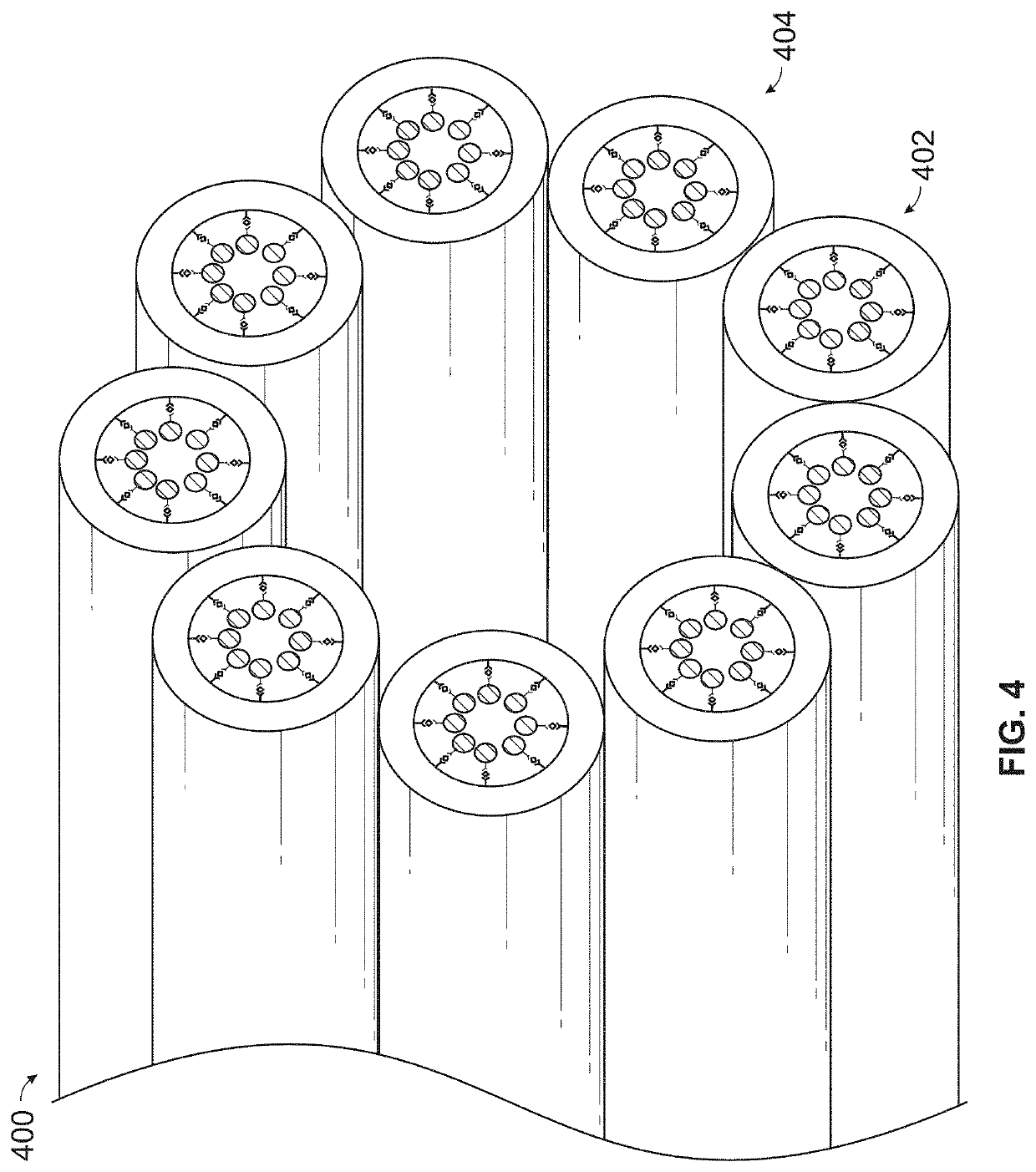
[0222]Example 3 is an example of a multi-core hollow polymer optical fiber, comprising multiple hollow cores (e.g. hollow channels within the fiber). The multi-core hollow polymer optical fiber provides for increased available surface area for analyte binding, and as well as decreased distance that an analyte or assay reagent needs to diffuse in order to reach the surface of the hollow polymer optical fiber. FIG. 15 is an image of a multi-core hollow polymer optical fiber. FIG. 15B is another image of the multi-core hollow polymer optic fiber. FIG. 15C is an image of an end facet of the multi-core hollow polymer optic fiber showing the multiple hollow cores of the fiber.

[0223]The multi-core hollow polymer optical fiber in this example is made of polystyrene, has an outer diameter of 1.3 mm and comprises 19 hollow channels of inner diameter of 105 μm, each of which was dyed with acceptor dye composition (e.g. comprisin...

example 4

on of a Hollow Polymer Optical Fiber for Dyeing of its Interior Surfaces with Acceptor Dye Compositions

[0224]Example 4 is an example of a process and system components for preparing a hollow polymer optical fiber in order to dope the fiber with acceptor and / or donor dye compositions. In the example process, in order to dope the fiber with acceptor and / or donor dye compositions, polymer optical fibers were connected to a syringe. The syringe is used to pump solutions comprising acceptor dye and / or donor dye compositions, as well as solutions (e.g. water, ethanol) for rinsing the interior of a fiber, into the fibers. The polymer optical fibers were connected to the syringe via an appropriate sized threaded tube fitting nut and ferrule. For a 1.3 mm polymer optical fiber, a 1 / 16th inch high-performance (pressure) liquid chromatography (HPLC) fitting can be used. The fitting nut was attached to a coupler that was then also attached to a syringe or syringe pump. FIG. 16 shows two images ...

example 5

e Interior of a Hollow Polymer Optic Fiber with an Acceptor Dye Composition

[0225]Example 5 is an example of a process for doping the interior of a length of hollow polymer optical fiber with an acceptor dye composition (e.g. comprising a chemiluminescent singlet oxygen acceptor and a fluorescent compound). In the example process, the acceptor dye composition comprises C28 thioxene and a europium chelate (Eu(NTA)3BINAPO).

[0226]A portion (600 μL) of an acceptor dye solution of Eu(NTA)3BINAPO and C28 thioxene in 2-ethoxyethanol, prepared as described in Example 2 above, was placed in a test tube and heated to 70° C. in an oil bath. In order to dope the interior of a hollow polymer optic fiber, 15 cm lengths of hollow polymer optical fiber, for example the 19-hole polymer optical fiber described in Example 3 above, were attached to a syringe as described in Example 4 above. The syringe was filled with 200 proof ethanol. The ethanol was pushed through the attached hollow polymer optical ...


PUM

PropertyMeasurementUnit
volumeaaaaaaaaaa
total weightaaaaaaaaaa
transfer distanceaaaaaaaaaa

Abstract

Presented herein are methods, systems, and apparatus for single analyte detection or multiplexed analyte detection based on amplified luminescent proximity homogeneous assay (“alpha”) technology, but using hollow polymer fiber optics doped with ‘acceptor bead’ dye (e.g., thioxene, anthracene, rubrene, and / or lanthanide chelates) or ‘donor bead’ dye (e.g., phthalocyanine) that carry a signal generated by the dopant via singlet oxygen channeling.

Description

RELATED APPLICATIONS[0001]The present disclosure claims priority to U.S. Provisional Patent 62 / 259,000, entitled “Hollow Polymer Fiber Optic System for Single Analyte and Multiplexed Analyte Detection,” and filed Nov. 23, 2015, the content of which is incorporated by reference in its entirety.TECHNICAL FIELD[0002]Presented herein are methods, systems, and apparatus for analyte detection. For example, methods, systems, and apparatus are described herein that use doped hollow polymer fiber optics to carry a signal generated by the dopant via singlet oxygen channeling for detection of one or more analytes in a sample.BACKGROUND[0003]There are a number of bead-based assay technologies used to study biomolecular interactions in a microplate format, for example, AlphaScreen® and AlphaLISA®, manufactured by PerkinElmer of Waltham, Mass. The acronym “Alpha” stands for amplified luminescent proximity homogeneous assay. These technologies are non-radioactive, homogeneous proximity assays. Bin...

Claims


Application Information

Patent Timeline
Patent Type & Authority Patents(United States)
IPC IPC(8): G01N33/552G01N21/64G01N21/77G01N33/543
CPCG01N21/7703G01N33/54373G01N21/77G01N21/64G01N2021/7709G01N2201/0221G01N2021/773G01N2021/7786G01N2021/6441G01N33/552
Inventor BOSSÉ, ROGERYARED, WAEL I.HARVEY, PETER A.GROVES, KEVINFAQIR, ILIASMELTZER, MICHAEL
Owner PERKINELMER HEALTH SCIENCES INC
Why Eureka
Try Eureka