Multi-fluid heat exchanger and method of making same

a heat exchanger and flue technology, applied in indirect heat exchangers, safety devices for heat exchange apparatus, lighting and heating apparatus, etc., can solve the problems of minute leakage at the interface of one or more baffles and the corresponding headers, gas buildup pressure, and possibility of cross contamination

Active Publication Date: 2006-08-29
MODINE MFG CO
View PDF32 Cites 28 Cited by
  • Summary
  • Abstract
  • Description
  • Claims
  • Application Information

AI Technical Summary

Benefits of technology

[0011]It is an object of the invention to provide a multi-fluid heat exchanger that can minimize the possibility of the formation of leaks and baffled headers that could result in cross contamination of the two or more heat exchange fluids.
[0012]It is an object of the invention to provide a multi-fluid heat exchanger and a method of manufacturing the same that can be readily adaptable to present day assembly techniques and thus may not require modification of assembly lines.

Problems solved by technology

One perceived difficulty in the fabrication of such a dual fluid heat exchanger resides in the possibility that if the heat exchanger is brazed during the fabrication process, the elevation of temperature may act upon gas within the dead tube and confined therein by the baffles, causing such gas to build up pressure and possibly cause minute leaks at the interface of one or more of the baffles and the corresponding header.
If such leaks occur in baffles on opposite sides of the dead tube, the possibility of cross contamination exists.
Moreover, there is no means by which any fluid that might leak into the space between the baffle can be readily discharged to avoid cross contamination.

Method used


Image

  • Multi-fluid heat exchanger and method of making same
  • Multi-fluid heat exchanger and method of making same

Examples


Embodiment Construction

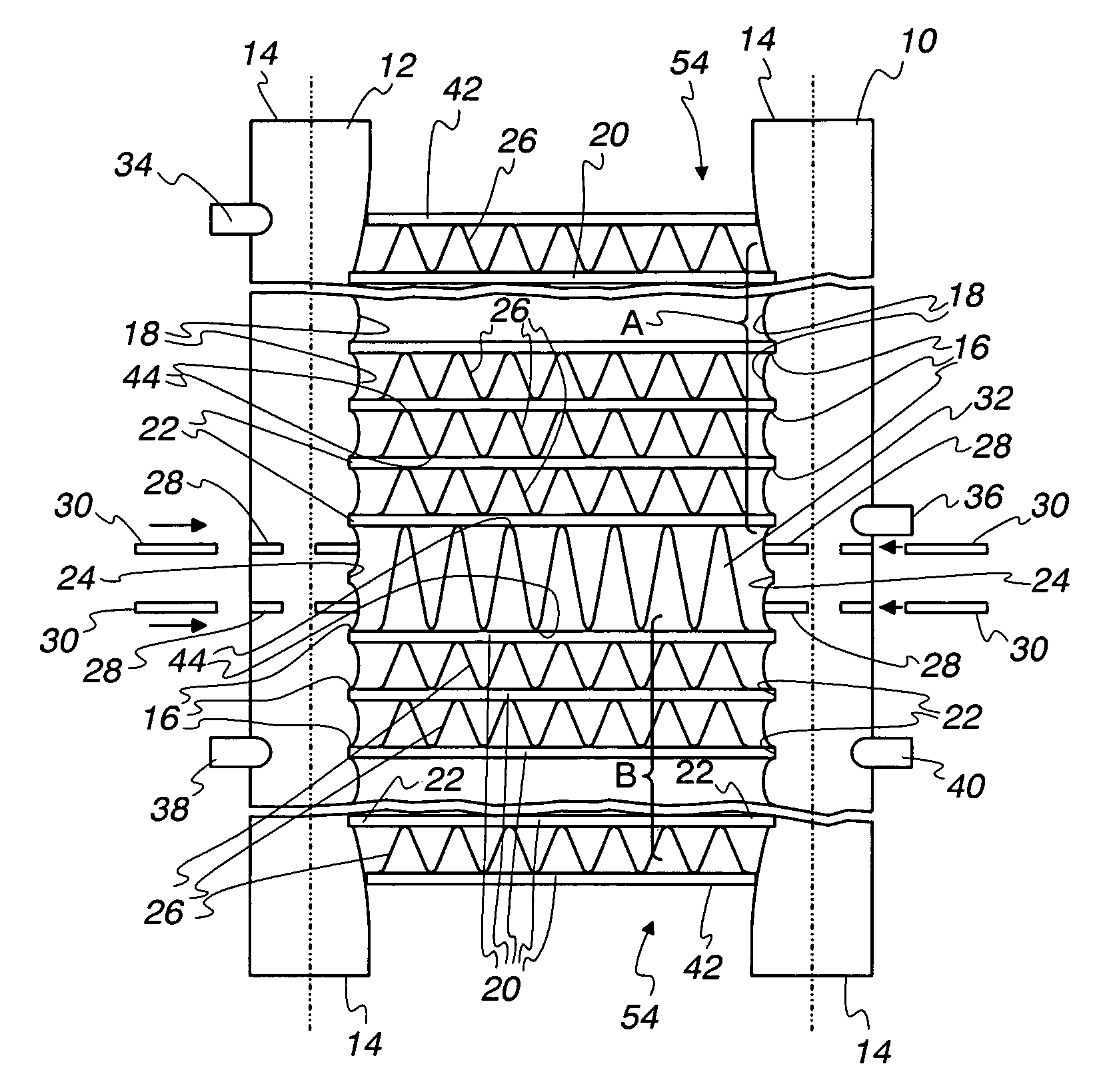
[0041]An exemplary embodiment of a dual fluid heat exchanger will be described herein in the environment of a vehicular application wherein the heat exchanger serves as a condenser or gas cooler for a refrigerant in a vehicular air conditioning system as well as an oil cooler. However, it is to be expressly understood that the inventive heat exchanger is not limited to use in vehicular applications nor is it limited strictly to cooling operations. Also, it is not limited to use with two fluids such as refrigerants and oil, but may be utilized with a variety of other fluids as well. Similarly, in the embodiment illustrated, each of the two fluids make a single pass through the heat exchanger. However, multiple passes may be envisioned for certain uses and can be provided by various means known in the art as for example, baffling systems, particularly in one tube row heat exchangers for forming multiple row heat exchangers wherein different passes occur in different rows. No limitatio...


PUM


Abstract

A multi-fluid heat exchanger having separate fluid flow paths for two fluid streams to be heated or cooled by a third fluid stream includes first and second elongated, parallel tubular headers (10, 12), having opposed ends (14), generally uniformly spaced elongated tube slots (16) in each of the headers (10, 12) with the tube slots (16) in one header (10) facing-and aligned with the tube slots (16) and the other header (12), a plurality of flattened tubes (20) extending between the headers (10, 12) and having ends (22) received in aligned ones of the tube slots (16), one tube slot (24) in each header being unoccupied by any of the flattened tubes (20), the one tube slots (24) being aligned with each other and located at a predetermined location between the ends (14) of the headers (10, 12) and between two groups (A, B) of the flattened tubes (20) so there are two groups of the flattened tubes (20) on each side of the one tube slot (24), a pair of baffles (30) in each header (10, 12) with one on each side of the one tube slot (24) and fins (26, 32) extend between and are in heat transfer relation with at least the adjacent tubes (20) in each of the groups (A, B).

Description

FIELD OF THE INVENTION[0001]This invention relates to heat exchangers, and more specifically, to a multi-fluid heat exchanger wherein two or more different heat exchange fluids are heated or cooled by a third heat exchange fluid.BACKGROUND OF THE INVENTION[0002]Multi-fluid heat exchangers such as two or dual fluid heat exchangers have been known for a considerable period of time. One typical usage for such heat exchangers is in vehicular applications for cooling two different heat exchange fluids. However, they may also be used in other applications wherein one or both of the two fluids may be heated by a third fluid as well.[0003]An early example of such a system intended for vehicular use is shown in U.S. Pat. No. 1,948,929 to Mac Pherson, issued Feb. 27, 1934. The Mac Pherson patent describes a dual fluid heat exchanger wherein part of the heat exchanger is used as a radiator to cool engine coolant while the remainder of the heat exchanger is utilized to cool a completely differe...

Claims


Application Information

Patent Timeline
Patent Type & Authority Patents(United States)
IPC IPC(8): F28D7/16F28F13/00F28D1/04F28F9/00F28F9/02
CPCF28D1/0443F28F9/0202F28F2265/12F28F2270/00F28F2009/0287F28D1/0408F28F9/00F28F9/0234F28D1/04
Inventor SCOVILLE, DAVID M.NAKAYAMA, KENGEBHARD, RICHARD T.
Owner MODINE MFG CO
Why Eureka
Try Eureka