
Hydrodynamic brake

a brake and hydraulic technology, applied in the direction of braking systems, rotary clutches, fluid couplings, etc., can solve the problems of laborious and relatively complicated fitting and servicing of components of conventional retarders, and achieve the effects of simple design, low cost and simple structur

Inactive Publication Date: 2006-08-29
SCANIA CV AB
View PDF16 Cites 0 Cited by
  • Summary
  • Abstract
  • Description
  • Claims
  • Application Information

AI Technical Summary

Benefits of technology

The present invention provides a hydrodynamic brake that is easy to access and fit. The brake has a structure with recesses that hold various components, such as valves, gear pumps, and accumulators. The recesses have openings in a common plane, making them easy to access. The brake also has a detachable second element that surrounds the components, allowing for quick servicing. The brake is designed to be sealed and prevent leakage of the medium. The technical effects of the invention are simplified fitting and servicing, easy access to components, and prevention of leakage.

Problems solved by technology

This renders the fitting and servicing of components of a conventional retarder laborious and relatively complicated.

Method used


Image

  • Hydrodynamic brake
  • Hydrodynamic brake

Examples


Embodiment Construction

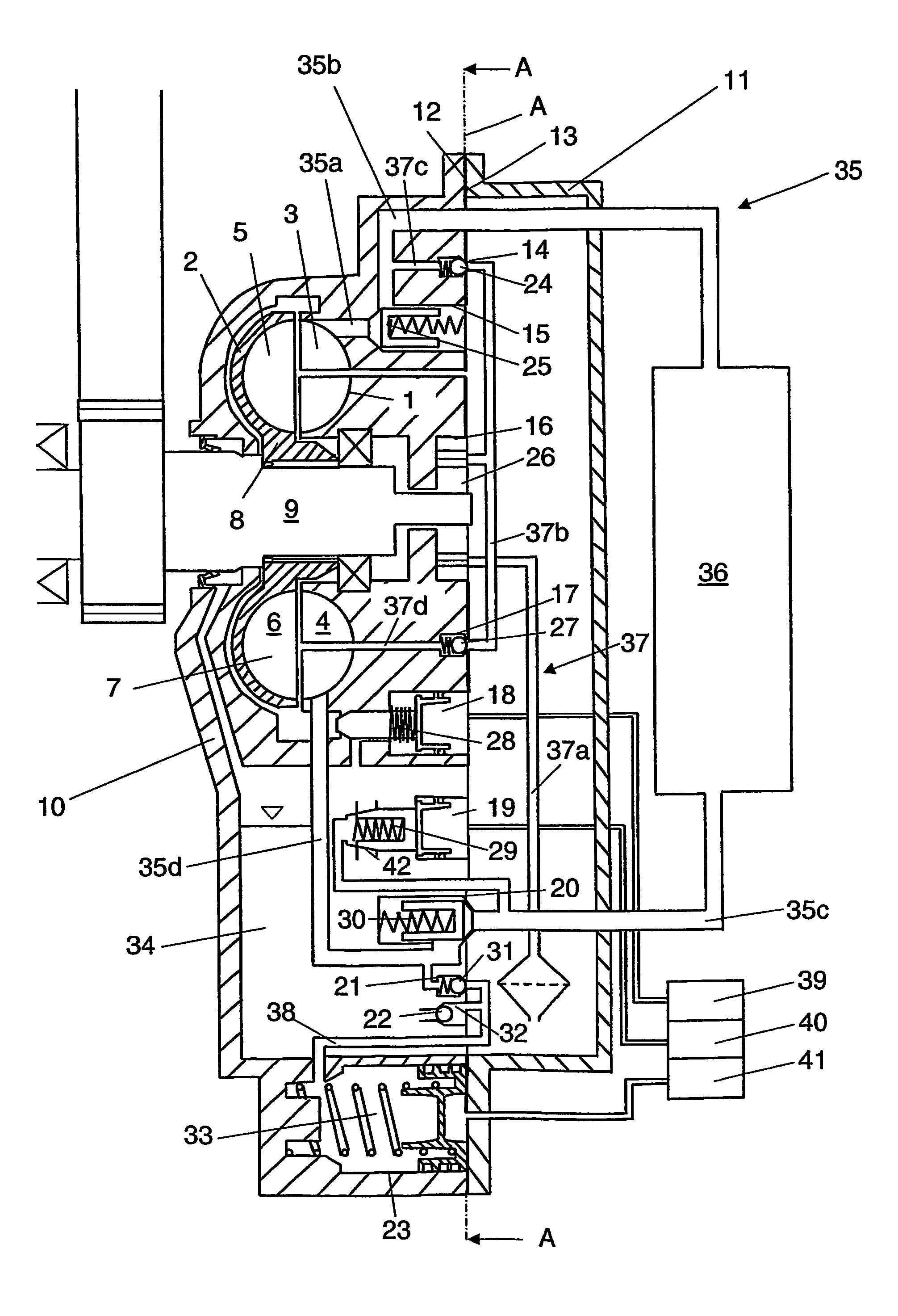
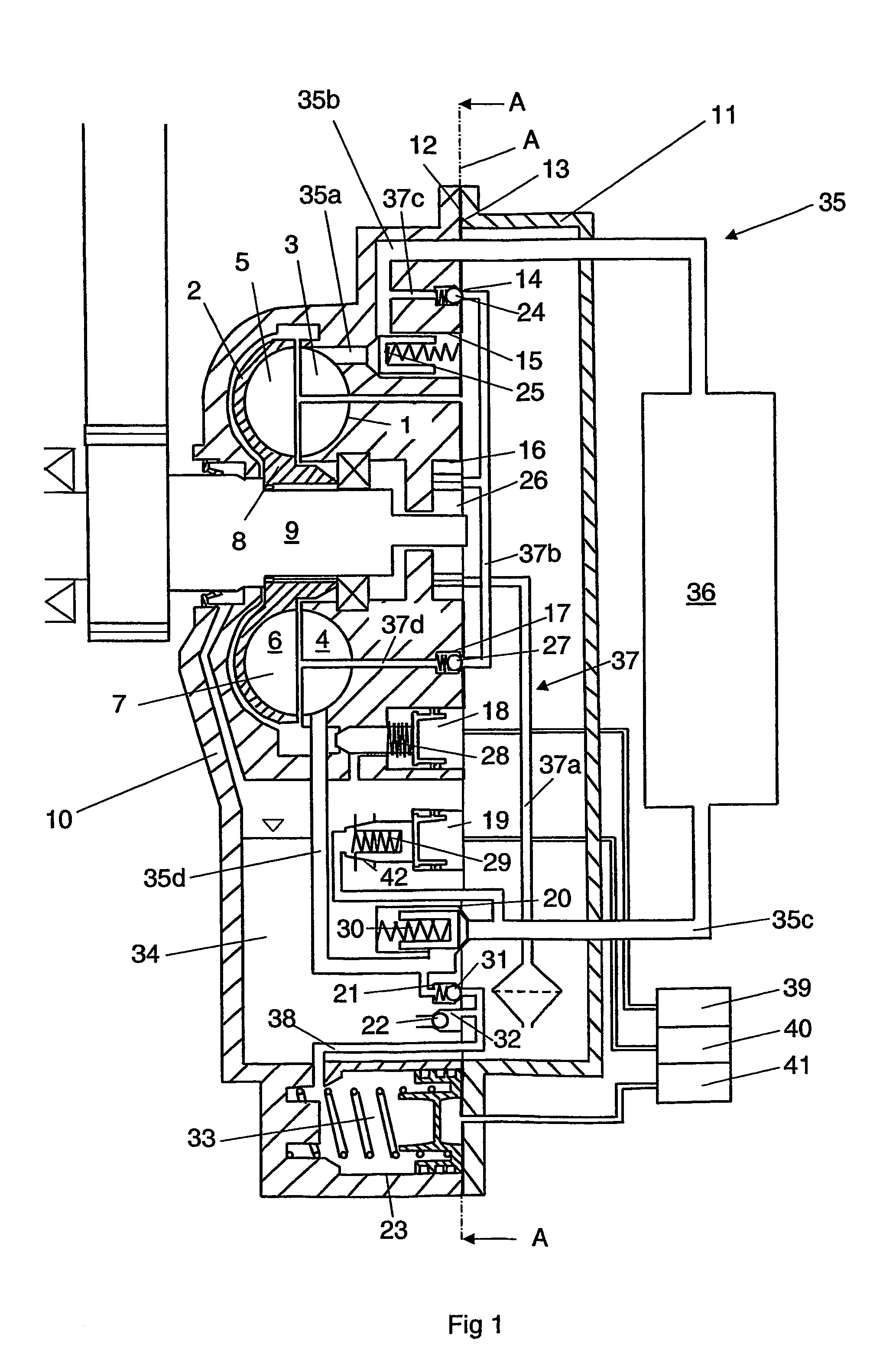
[0010]FIG. 1 depicts a hydrodynamic brake in the form of a retarder of a powered vehicle. The retarder comprises a stator 1 and a rotor 2. The stator 1 has an annular shell 3 with a multiplicity of blades 4 arranged at uniform spacing along the annular shell 3. The rotor 2 is of corresponding design with an annular shell 5 which incorporates a multiplicity of blades 6 likewise arranged at uniform spacing along the annular shell 5. The respective shells 3, 5 of the stator 1 and rotor 2 are coaxially arranged with respect to one another so that they together form a toroidal space 7. The rotor 2 incorporates a shaft portion 8 which is firmly connected to a rotatable shaft 9. The rotatable shaft 9 is itself connected to an appropriate driveshaft of the vehicle's driveline. The rotor 2 will thus rotate together with the vehicle's driveline.

[0011]The retarder depicted in FIG. 1 incorporates a housing which comprises a first element 10 and a second element 11. The first element 10 incorpor...


PUM


Abstract

The present invention relates to a hydrodynamic brake which comprises a stator, a rotor, a toroidal space defined by the stator and the rotor, a medium which is intended to be supplied to the toroidal space when the brake is activated, and a multiplicity of components for allowing regulation of the flow of the medium to and from the toroidal space. The hydrodynamic brake incorporates a structure with a multiplicity of recesses which each have an opening in a substantially common plane and each is intended to accommodate one of the components.

Description

BACKGROUND TO THE INVENTION, AND STATE OF THE ART[0001]The invention relates to a hydrodynamic brake and particularly to structures housing components of the brake.[0002]Hydrodynamic brakes such as retarders incorporate not only a stator and a rotor but also a number of components which are necessary for ensuring proper functioning of the retarder. Such components may comprise valves of various kinds which regulate the oil flow in a number of pipe circuits for the retarder. Another component is a pump (which may be a gear pump) which is required for transferring oil from an oil sump. A further component is an accumulator which caters for rapid filling of the retarder when necessary. Conventional retarders are usually constructed in such a way that the majority of said components are relatively dispersed in the retarder. This renders the fitting and servicing of components of a conventional retarder laborious and relatively complicated.SUMMARY OF THE INVENTION[0003]The object of the ...

Claims


Application Information

Patent Timeline
Patent Type & Authority Patents(United States)
IPC IPC(8): F16D57/02B60T1/087B60T10/02F16D57/04
CPCF16D57/04B60T10/02
Inventor FARM, JOHNNYJONSSON, HANSHERMELIN, GUNNAR
Owner SCANIA CV AB
Learn More