
Fitment and bottle

a technology applied in the field of fitting and bottle, can solve the problem of difficult pouring out of the container, and achieve the effect of reducing the amount of residual produ

Active Publication Date: 2006-08-29
HENKEL IP & HOLDING GMBH
View PDF23 Cites 32 Cited by
  • Summary
  • Abstract
  • Description
  • Claims
  • Application Information

AI Technical Summary

Benefits of technology

[0013]The present invention is directed to a fitment and a bottle body and to the container including fitment, bottle body and / or closure which can minimize the amount of residual product which remains in the container once its contents have been substantially depleted. The fitment of the invention comprises an outer wall, a bottom wall and a pour spout extending upwardly from the bottom wall. The outer wall includes a vent hole which also acts as a product exit aperture, preferably spaced from the bottom wall when the bottle is nearly fully inverted. More preferably, at least 40% of the area of the product exit aperture is contained within an upper half of the outer wall, still more preferably at least 50% of the area, more preferably at least 70% of the area and most preferably at least 80% of the area is contained within the upper half of the outer wall. If desired, additional product exit apertures may be present. Generally, it will be desirable that the bottom wall itself includes one or more product drainage apertures.
[0014]In accordance with the invention, a bottle body is provided which extends upwardly from a base and ends in a bottle finish. The finish includes one or more inner locking surfaces disposed to abut the outer wall of the fitment and an inner channel in one or more of the locking surfaces which is positioned to lead product which is disposed between the outer wall of the fitment and inner aspects of the finish when the container is inverted, to the product exit aperture and then out of the bottle and or directly out of the bottle. In one embodiment, the channel extends to the level of the product exit aperture, e.g. to the level of the top end (when the bottle is inverted) of the product exit aperture. Alternatively, the channels in the locking surfaces can extend through the locking surfaces to the exterior of the container. By use of a channel, it is possible for most of the last remnants of product to be poured from the container when it is in an inverted position, notwithstanding the abutting locking surface(s) on the finish which would otherwise tend to block or severely limit egress of residual product from the container. Since the fit between the locking surface(s) and the outer fitment base is not liquid-tight, the channel is particularly useful for promoting egress from the container of product trapped, or which would otherwise be trapped, between the locking surface(s) and the outer wall of the fitment.

Problems solved by technology

While drainback containers have enhanced the convenience of the use of heavy duty liquid detergents and other products, still some problems exist.
The problem which this presents is that it is sometimes difficult to pour out from the container the last remnants of product since product becomes entrapped between the fitment and the container finish when the bottle is in the inverted, pouring position.
This is particularly a problem for “see-through” containers, which can be expected to maximize consumer frustration with the inability to utilize the entire product present within the container.

Method used


Image

  • Fitment and bottle
  • Fitment and bottle
  • Fitment and bottle

Examples


Embodiment Construction

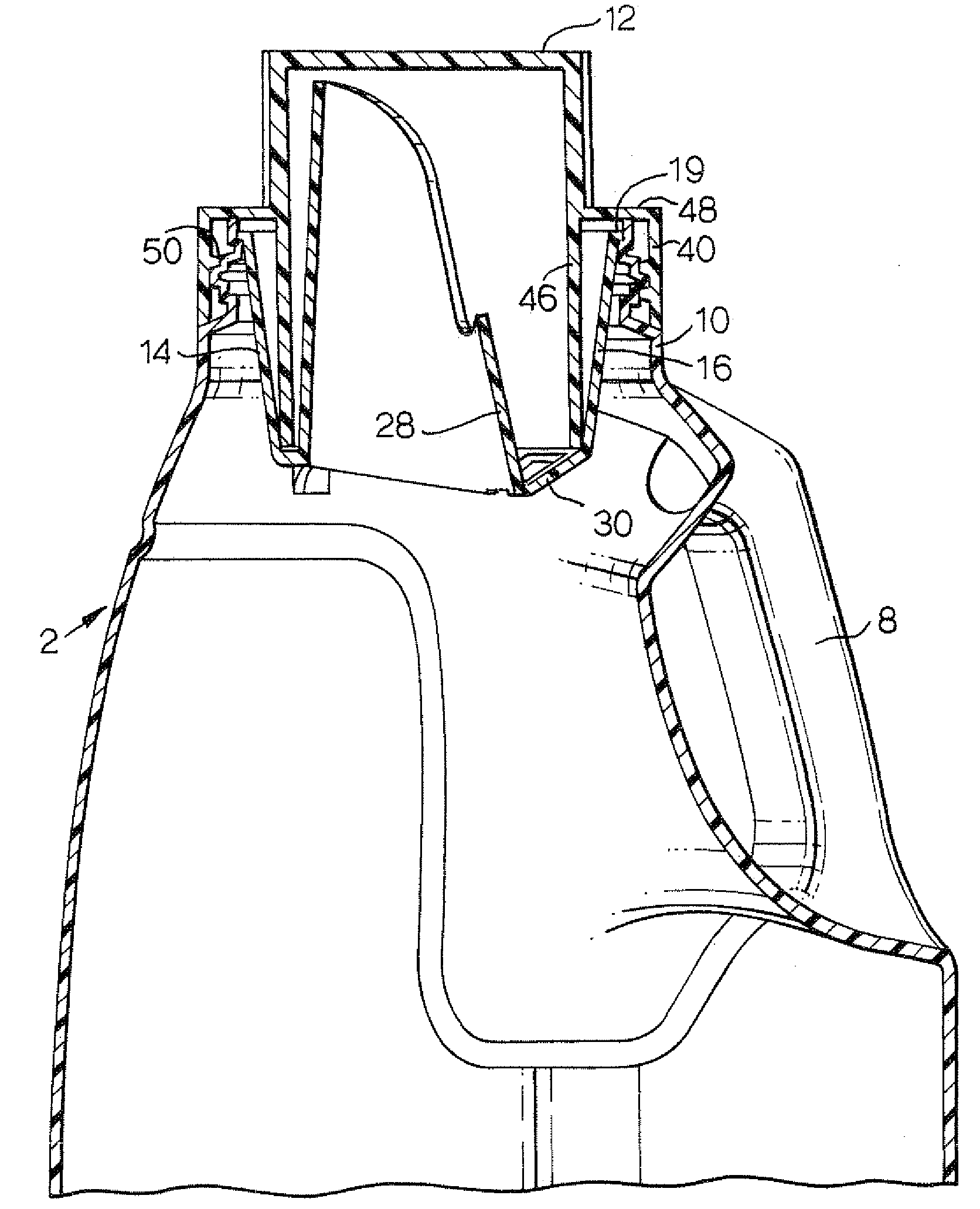
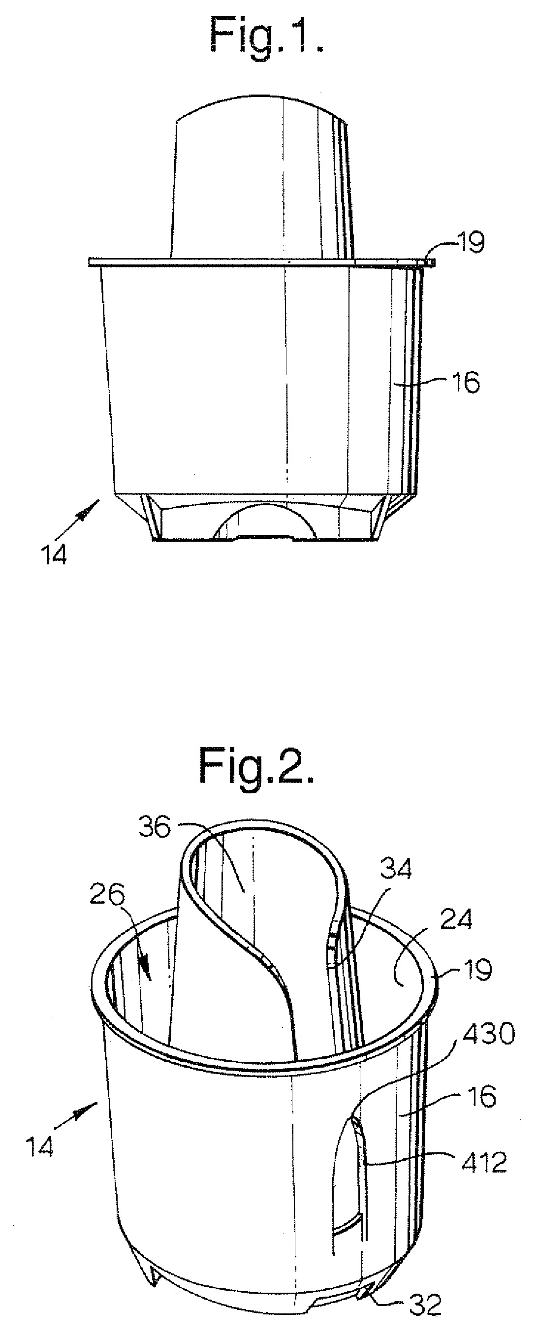
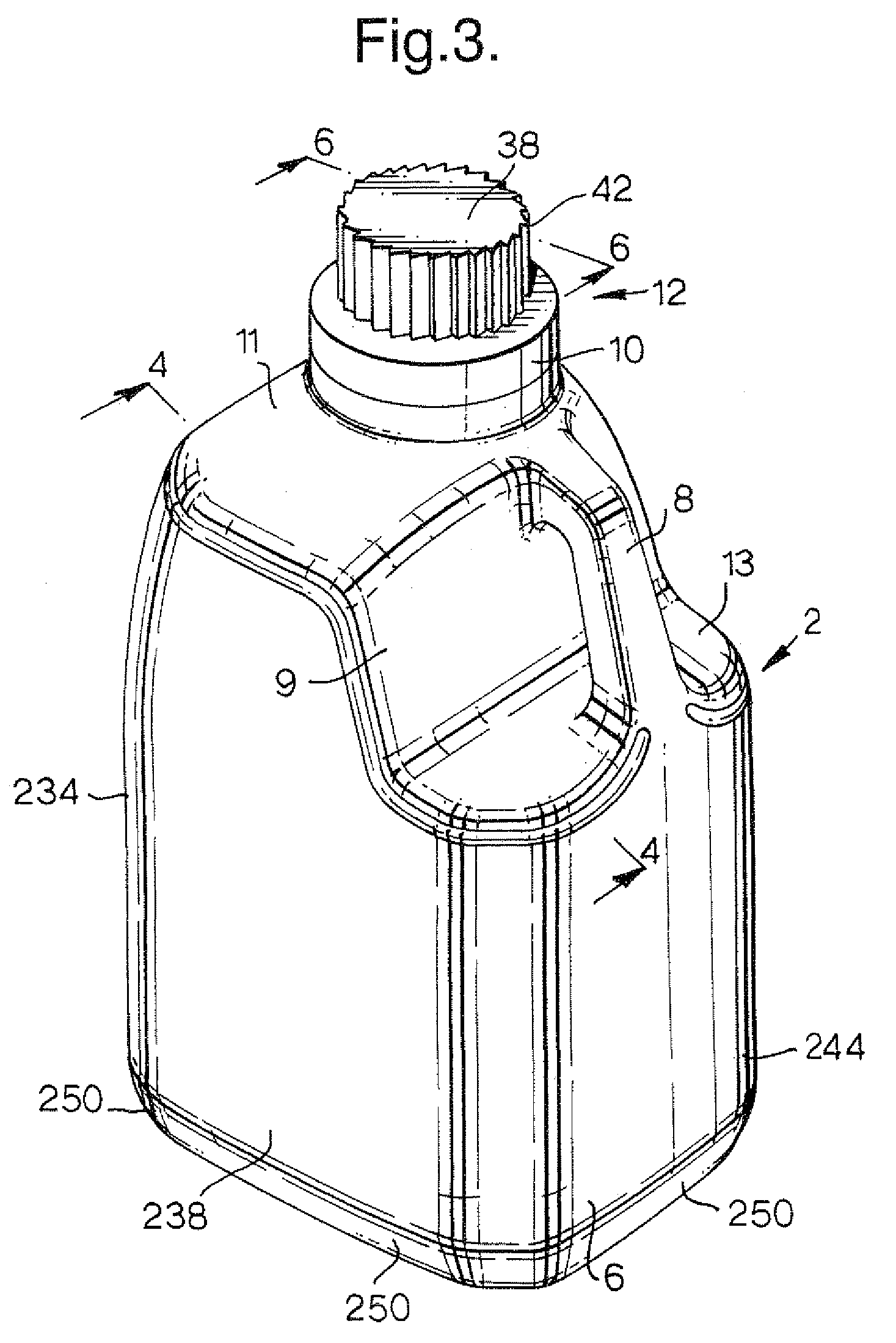
[0032]Referring now particularly to FIGS. 3 and 4, there is shown a container 2 including a bottle 6 having an integral handle 8 and a neck 10. The container 2 also includes a drainback fitment 14. Fastened to the top of the container 2, as viewed in FIG. 3, there is a closure or cap 12. All of the foregoing components are preferably molded from a resilient flexible plastic material. The materials may be selected so that the plastic from which the drainback fitment 14 is molded is softer than the materials from which the bottle 6 and closure 12 are formed. Alternatively, the drainback fitment may be made of a material of comparable hardness to that of the polypropylene of which the closure is generally made, e.g., LDPE (or HDPE).

[0033]The drainback fitment has an outer, frustoconical wall portion 16 which gradually tapers downwardly and inwardly and is received within the neck 10 of the bottle 6. The wall portion 16 terminates at its upper end in an annular rim 19. Rim 19 is general...


PUM


Abstract

A container including a fitment having an outer wall and a pour spout. The fitment outer wall includes a first product exit aperture. A bottle finish includes one or more locking surfaces abutting the outer wall of the fitment, and the finish locking surface includes a channel which directs product trapped between the outer wall of the fitment and the inner wall of the finish to the first product exit aperture and then to the exterior of the container or directly to the exterior of the container. This permits egress of residual drops of product from the container. Alternatively, the channel can extend to the top of the finish.

Description

BACKGROUND OF THE INVENTION[0001]Heavy duty liquid detergent products have grown in popularity over recent years. The sale of such products in specialized dispensing packages, usually including a combined measuring cup / closure, and a drainback fitment / spout has aided the consumers in the use of such products.[0002]While drainback containers have enhanced the convenience of the use of heavy duty liquid detergents and other products, still some problems exist. Many of the containers include fitments which extend well below the top of the container finish into the bottle. The problem which this presents is that it is sometimes difficult to pour out from the container the last remnants of product since product becomes entrapped between the fitment and the container finish when the bottle is in the inverted, pouring position. This is particularly a problem for “see-through” containers, which can be expected to maximize consumer frustration with the inability to utilize the entire product...

Claims


Application Information

Patent Timeline
Patent Type & Authority Patents(United States)
IPC IPC(8): B67D1/16B65D47/12B65D47/40
CPCB65D47/122B65D47/40
Inventor GIBLIN, EDWARD JOHNSASO, CORINNEALBRIGHT, GEORGE
Owner HENKEL IP & HOLDING GMBH
Learn More