Compound automotive rearview mirror

a rearview mirror and composite technology, applied in the field of mirrors, can solve the problems of insufficient adjacent lane visibility of the fmvss 111, insufficient glance over the shoulder, and inability to view adjacent lanes,

Active Publication Date: 2006-08-29
PLATZER KATALINA
View PDF110 Cites 179 Cited by
  • Summary
  • Abstract
  • Description
  • Claims
  • Application Information

AI Technical Summary

Benefits of technology

[0021]In another embodiment of the invention, an auxiliary blindzone viewing mirror can be inserted into a cut-out region of a main viewing mirror. The auxiliary blindzone viewing mirror can comprise a convex reflective surface optimized in size and orientation to provide primarily only a view of the blindzone while leaving the region surrounding it available to meet the requirements of FMVSS 111. The auxiliary blindzone viewing mirror having a rim about its perimeter for resting against a surface of the main viewing mirror. The rim can be canted to obscure the reflection of the auxiliary blindzone viewing mirror in the main viewing mirror.

Problems solved by technology

Early in this century however, both inside and outside mirrors were added to automotive vehicles to provide rearward and limited lateral visibility.
However, it is deficient in that it is unable to view the adjacent lanes at distances of less than one to two car lengths to the rear.
Unfortunately, outside mirrors meeting FMVSS 111 still do not provide adequate adjacent lane visibility to view cars that are in the range of one car length to the rear.
Even a glance over the shoulder may not be adequate to observe a vehicle in the blindzone.
Furthermore, this obstruction is not obvious to most drivers, and they may assume that the “over the shoulder glance” has allowed them to see the blindzone when in reality it has not.
Spherically convex mirrors provide a wide field of view, but at the penalty of a reduced image size.
Simply placing a round segment of a convex mirror on the main mirror surface, as is commonly done with stick-on convex mirrors, does not solve the problem.
Doing so can provide a view to the rear which includes the blindzone, but it will also show much of the side of the car, the sky and the road surface, which are distracting and extraneous to the safe operation of the vehicle.
In this way, if the driver sees a vehicle in the blindzone-viewing mirror, he knows it is unsafe to move into the adjacent lane.
Other problems with add-on mirrors are that they:may interfere with the requirements of FMVSS 111;may substantially decrease the plane main mirror viewing angle;interfere with cleaning, especially when there is ice on it; andappear as an unsightly excrescence on the main mirror.

Method used


Image

  • Compound automotive rearview mirror
  • Compound automotive rearview mirror
  • Compound automotive rearview mirror

Examples


Embodiment Construction

)

[0056]As required, detailed embodiments of the present invention are disclosed herein. However, it is to be understood that the disclosed embodiments are merely exemplary of an invention that may be embodied in various and alternative forms. Therefore, specific functional details disclosed herein are not to be interpreted as limiting, but merely as a representative basis for the claims and / or as a representative basis for teaching one skilled in the art to variously employ the present invention.

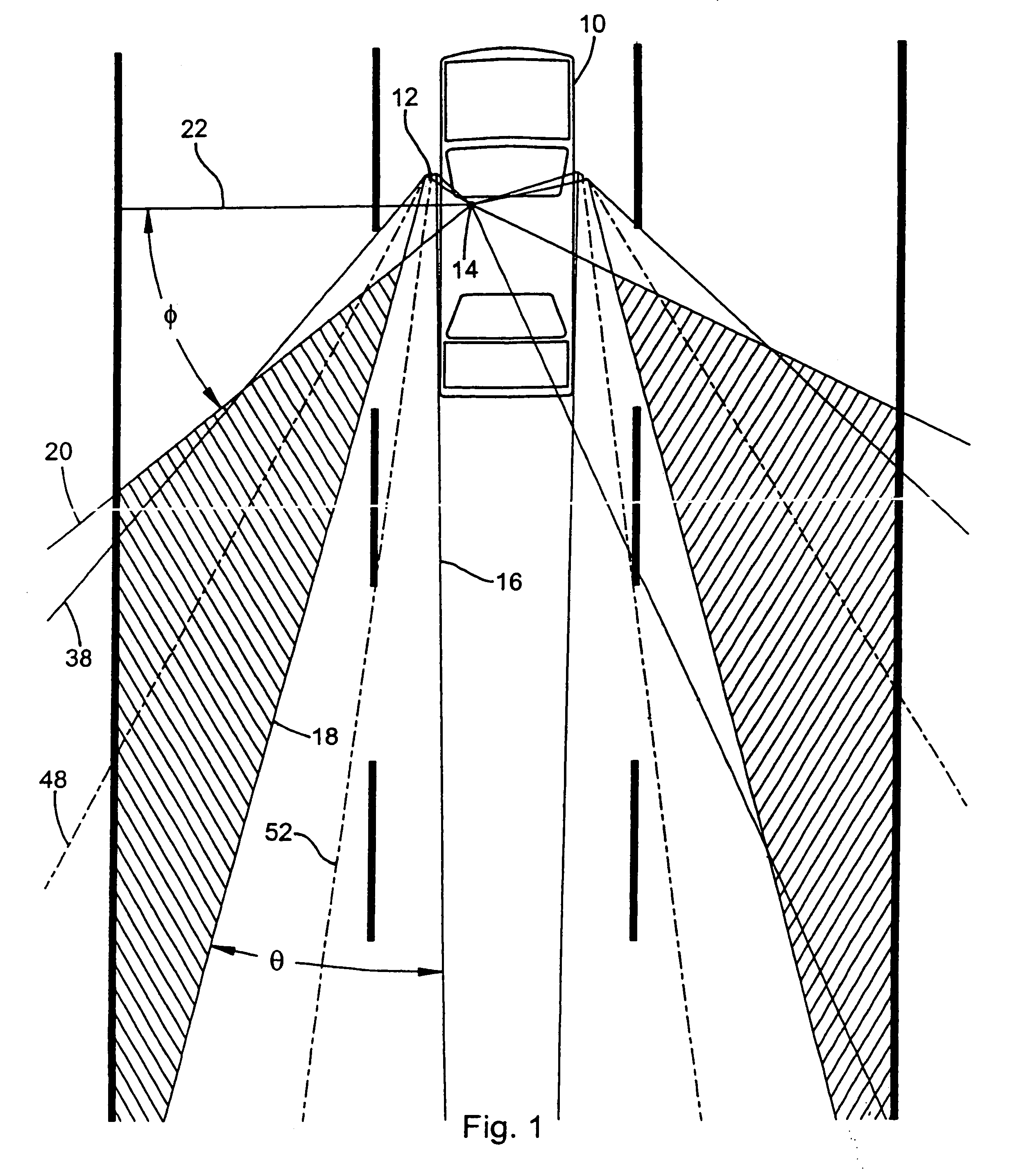
[0057]Referring now in greater detail to the drawings, FIG. 1 shows a mid-sized passenger car 10 in the middle lane of a three-lane highway with 12-foot wide lanes. The vehicle 10 is equipped with a driver's side outside mirror 12. The driver's eyes are shown centered at point 14, from which the driver has a field of view to the rear in the horizontal plane encompassing the acute angle formed by lines 16 and 18. Line 20 defines the rearward limit of the driver's peripheral vision when lookin...


PUM


Abstract

A composite mirror adapted for use as an outside rearview mirror of a motor vehicle includes a main or primary viewing mirror and an auxiliary blindzone viewing mirror juxtaposed to expose the vehicle blindzone to the vehicle operator. The main viewing mirror is generally of unit magnification. The auxiliary mirror is generally composed of a convex surface that can be either attached atop the surface of the main viewing mirror or placed within a cut-out region of the main viewing mirror. The auxiliary mirror can be partially recessed below the surface of the main viewing mirror and can have a skirt for minimizing undesirable reflections in the main viewing mirror.

Description

[0001]This application claims the benefit of U.S. provisional application Ser. No. 60 / 449,370, filed Feb. 21, 2003.BACKGROUND OF THE INVENTION[0002]1. Field of the Invention[0003]The present invention relates generally to mirrors having multiple surfaces of differing magnification and, particularly, to the application of such mirrors as external side rearview automotive operator aides.[0004]2. Background Art[0005]Originally, motor vehicles, particularly passenger cars, did not have mirrors to assist the driver. Early in this century however, both inside and outside mirrors were added to automotive vehicles to provide rearward and limited lateral visibility. As the number of vehicles and driving speeds increased, rearward visibility became ever more important.[0006]Today, all passenger cars have a mirror centrally located inside the vehicle. This mirror is the primary mirror. It provides a wide viewing angle, giving an excellent view to the adjacent lanes at a distance of two or more...

Claims


Application Information

Patent Timeline
Patent Type & Authority Patents(United States)
IPC IPC(8): G02B5/10B60R1/08
CPCB60R1/082
Inventor PLATZER, JR., GEORGE E.
Owner PLATZER KATALINA
Why Eureka
Try Eureka