Vortex type gas lamp

a gas lamp and vortex technology, applied in the field of vortex type gas lamps, can solve the problems of rotary swirling motion of gases in the chamber

Inactive Publication Date: 2006-08-29
CHESNEY PETER
View PDF16 Cites 64 Cited by
  • Summary
  • Abstract
  • Description
  • Claims
  • Application Information

AI Technical Summary

Problems solved by technology

This results in a rotary swirling motion of the gases in the chamber.

Method used


Image

  • Vortex type gas lamp
  • Vortex type gas lamp
  • Vortex type gas lamp

Examples


Embodiment Construction

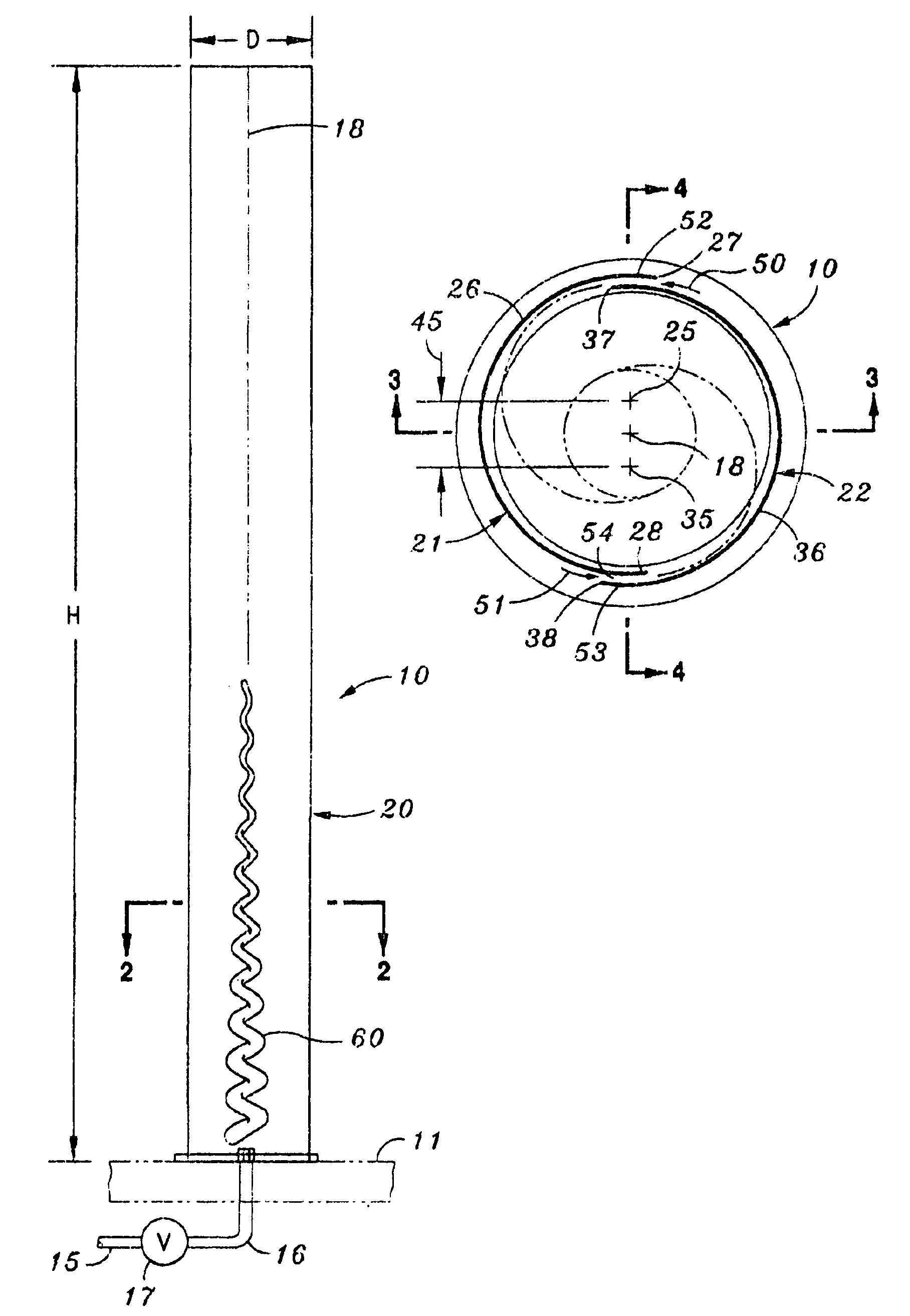
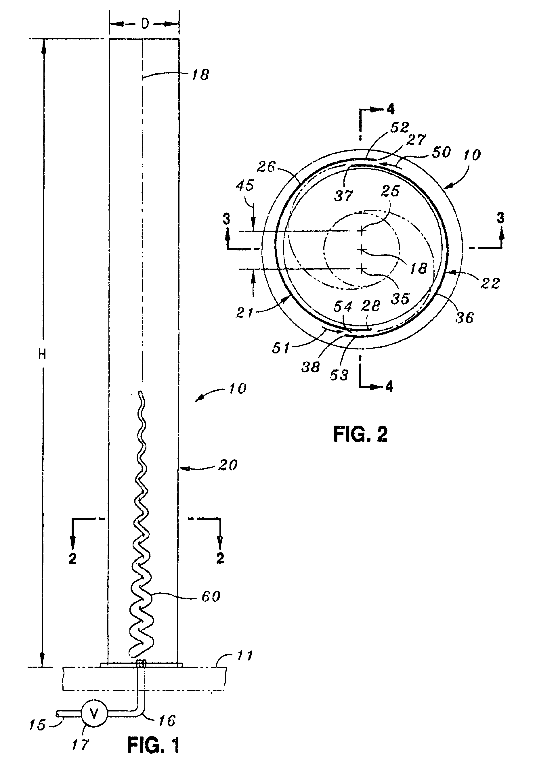
[0014]The presently preferred embodiment of this invention is shown in FIG. 1. A gas lamp 10 rests on any suitable support 11 such as a table, fireplace, or wall. A source 15 of combustible gas is supplied under pressure through a conduit 16. A control valve 17 admits or prevents the admission of gas, and controls its rate of flow. A mixing burner or mixing nozzle is not needed. The air is supplied through the gaps in the wall structure.

[0015]The lamp is shown in an upright position, with its central axis 18 vertically oriented. Exact upright orientation is not necessary. It may be slanted downwardly, up to about 45 degrees from the vertical. Beyond that, the advantages of improved convection are lost, and the lamp is not as reliable.

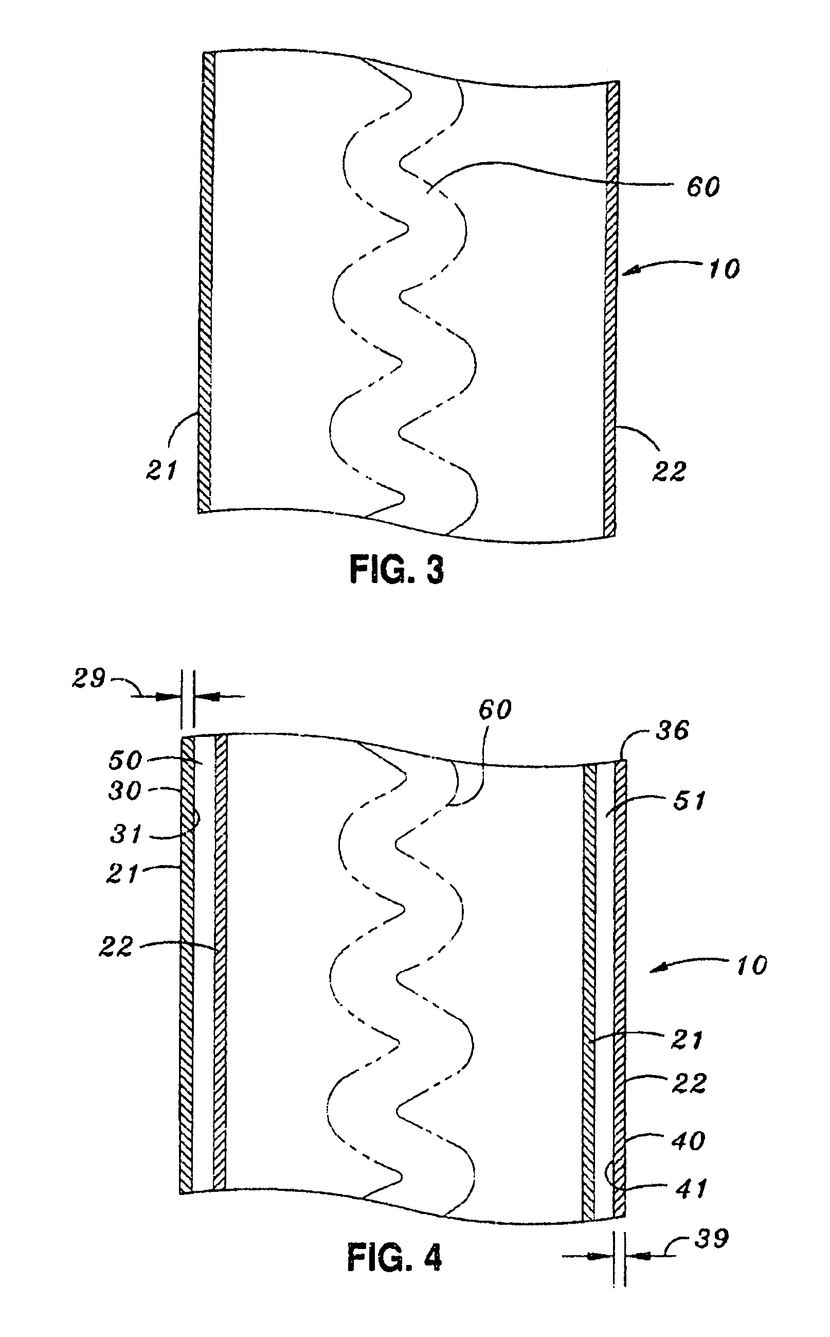
[0016]This lamp is characterized by its elegant simplicity. It may be formed by as few as two parts, and usually will be. It is possible to use three or more, but there is no particular advantage in doing so, although it is within the scope of this inve...


PUM


Abstract

A vortex type gas lamp comprising a base and an axially extending-transparent shield. Gas is supplied near the bottom end of the shield. The shield is formed of a plurality (preferably two) axial curved sections which overlap one another at their axial edges to form tangentially directed port. Combustion of the gas with atmospheric oxygen admitted through the ports results in an axial vortex of burning gas useful for illumination, decoration and heat.

Description

FIELD OF THE INVENTION[0001]A gas lamp which utilizes combustible gas burned as a linear vortex to produce light along a substantial flame length for illumination, comfort, mood, decoration and large scale art.BACKGROUND OF THE INVENTION[0002]Combustion flames have historically been used for their radiant and convective heating effects, and for illumination. Hearth fires, campfires, and fire rings are classical examples. The combustion of wood, coal, natural gas and bottled gas is generally the source of the flame.[0003]The shape of the flame is rarely of interest in most applications where warmth, mood and “coziness” are the principal objectives. The flame itself usually will be in a confined (but vented) region, and much of the heat from the reverse side of the flame will be re-radiated by surrounding surfaces. However, much of the light and some of the radiant heat will be dissipated or hidden from view. In addition, the height of the flame may be quite low, and its illumination ...

Claims


Application Information

Patent Timeline
Patent Type & Authority Patents(United States)
IPC IPC(8): F23C7/00F23Q2/32F23D1/00F23D14/24
CPCF23C7/002F23D14/24F23D2206/0068
Inventor CHESNEY, PETER
Owner CHESNEY PETER
Why Eureka
Try Eureka