Electric heating device with heating zones

a heating device and electric heating technology, applied in the direction of heater elements, ohmic resistance electrodes, air heaters, etc., can solve the problems of high electric energy needlessly converted into power, disadvantages of conventional auxiliary electric heating and vehicle air conditioning units, and engine not providing the amount of heat needed for heating the interior of the vehicle, etc., to achieve low manufacturing cost of electric heating devices, easy modification, and easy clipping

Inactive Publication Date: 2006-08-29
CATEM
View PDF4 Cites 23 Cited by
  • Summary
  • Abstract
  • Description
  • Claims
  • Application Information

AI Technical Summary

Benefits of technology

[0012]Another advantage of the present invention is to be seen in the fact that the heating device in question has external dimensions which are identical to those of hitherto used heating devices, so that it can be integrated in air conditioning units having a conventional structural design, without any changes being necessary.
[0013]Each group of separately controllable PTC heating elements has preferably associated therewith a separate radiator element. This will effectively prevent neighbouring zones from being heated as well.
[0014]Each group of separately controllable PTC heating elements is preferably supplied with current via a separate contact sheet, the respective contact sheets being arranged in the same plane. In this way, a separate control can be achieved without any external structural modifications and without restricting the amount of air passing through the unit.
[0015]When two groups of separately controllable PTC elements are provided, the respective electric connections for the contact sheets can be arranged on opposed narrow sides. Preferably, the respective electric connections are provided on the same narrow side, the current supply means used for supplying current to the PTC heating elements, which represent the rear PTC heating elements when seen from the connections, extending laterally relative to the front contact sheet. In this way, current can be supplied to both groups of heating elements without a

Problems solved by technology

When the engine operates in the lower partial-load range and when outside temperatures are low, e.g. in winter, the engine does not supply the amount of heat required for heating the vehicle interior.
These conventional auxiliary electric heatings and vehicle air conditioning units are disadvantageous insofar as an individual supply of heat to the respective “zones” cannot be effected separately.
It f

Method used


Image

  • Electric heating device with heating zones
  • Electric heating device with heating zones
  • Electric heating device with heating zones

Examples


Embodiment Construction

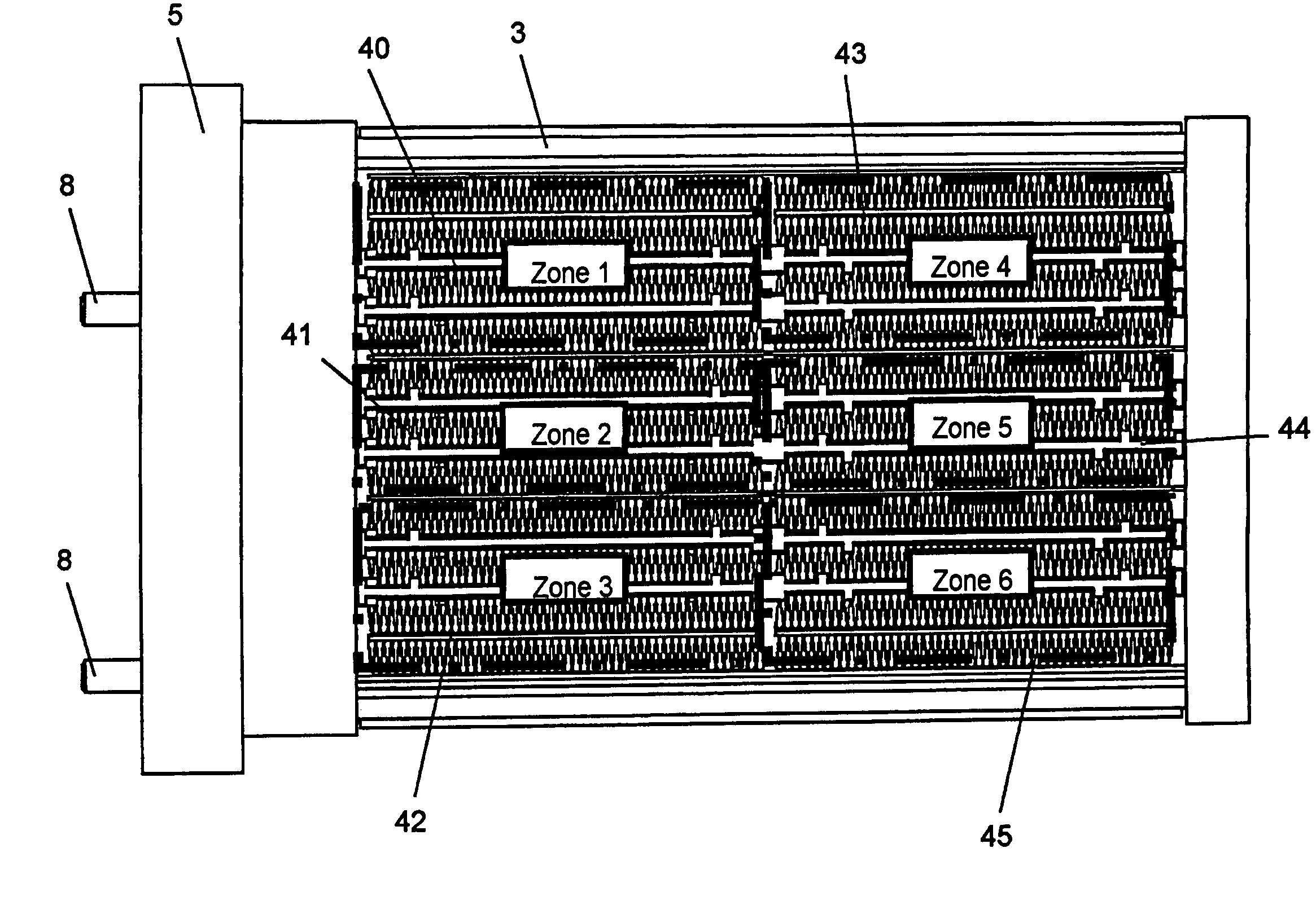
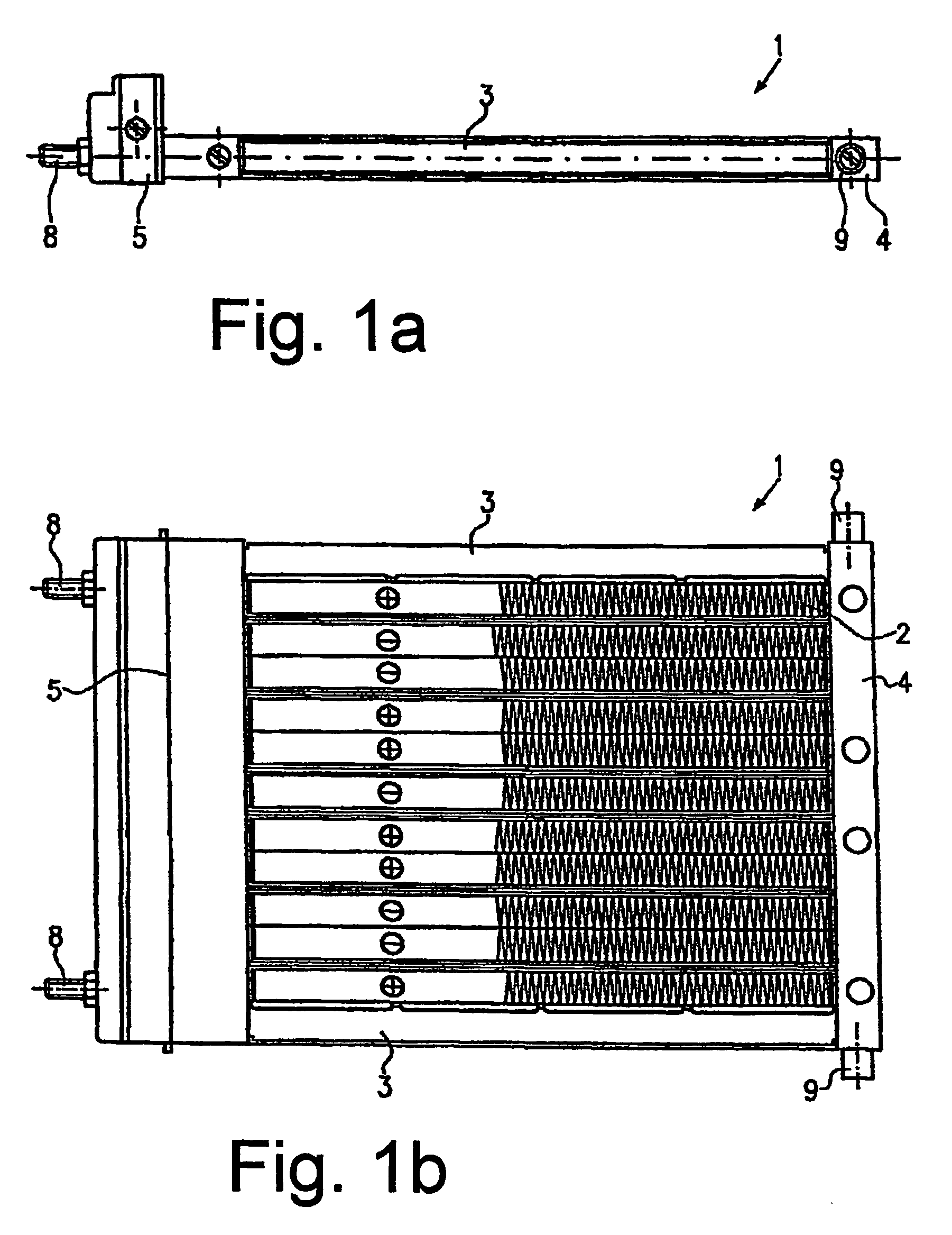
[0034]The structural design of an electric heating device, which is adapted to be used especially in motor vehicles, is shown in FIG. 1a and FIG. 1b. Whereas FIG. 1b is a top view of the electric heating device, the view shown in FIG. 1a is a side view. The electric heating device 1 is provided with a heating register comprising a plurality of layered or stacked heating elements. Each heating element comprises at least one resistance heating element and radiator elements or heat conducting sheets arranged adjacent thereto. The elements used as resistance heating elements are preferably PTC heating elements. The heating register is held in a frame comprising opposed longitudinal bars 3 and lateral bars 4 and 5 which are arranged at right angles to these longitudinal bars 3. The frame bars are made of metal or of plastic material.

[0035]The longitudinal bars have essentially identical structural designs. The opposed lateral bars 4 and 5, however, differ insofar as the lateral bar 5 is ...


PUM


Abstract

An electric heating device is adapted to be used in particular as an auxiliary electric heating for motor vehicles. The heating device comprises a plurality of PTC heating elements arranged in a plane of said heating device. The PTC heating elements are in electric contact with contact sheets for supplying current thereto and in thermal contact with radiator elements for transferring the heat produced to an air current to be heated. According to the present invention, the PTC heating elements arranged in this plane are adapted to be controlled separately in at least two groups.

Description

BACKGROUND OF THE INVENTION[0001]1. Field of the Invention[0002]The invention relates to an electric heating device for motor vehicles. In particular, the invention relates to an electric heating device provided with a heating register which comprises separately controllable heating zones.[0003]2. Description of the Related Art[0004]In motor vehicles, and in particular in motor vehicles with consumption-optimized internal combustion engines, electric heating devices are used for heating the vehicle interior and the engine. Such electric heating devices are, however, also suitable to be used for room air conditioning, for industrial plants, household appliances, etc.[0005]The improved efficiency of consumption-optimized internal combustion engines causes a substantial reduction of the heating power in motor vehicles. When the engine operates in the lower partial-load range and when outside temperatures are low, e.g. in winter, the engine does not supply the amount of heat required fo...

Claims


Application Information

Patent Timeline
IPC IPC(8): H05B3/00B60H1/03H05B3/02B60H1/22F24H3/04H05B3/03H05B3/06H05B3/10H05B3/14H05B3/50
CPCB60H1/2225F24H9/1872H05B3/14H05B3/50F24H3/0429B60H2001/2237B60H2001/2287H05B2203/02H05B3/10
Inventor BOHLENDER, FRANZCLAUSS, MAURICENIEDERER, MICHAEL
Owner CATEM
Why Eureka
Try Eureka