Capacitance change detection device

a detection device and capacitance technology, applied in the direction of anti-theft devices, instruments, pulse techniques, etc., can solve the problem that the sensitivity of the capacitance variation to be measured depends on the environmen

Active Publication Date: 2006-08-29
AISIN SEIKI KK
View PDF11 Cites 60 Cited by
  • Summary
  • Abstract
  • Description
  • Claims
  • Application Information

AI Technical Summary

Problems solved by technology

In other words, there is a drawback that sensitivity regarding variations of capacitance to be measured depends on the environment.

Method used


Image

  • Capacitance change detection device
  • Capacitance change detection device
  • Capacitance change detection device

Examples


Embodiment Construction

[0021]Embodiments of the present invention will be explained with reference to illustrations of drawing figures as follows.

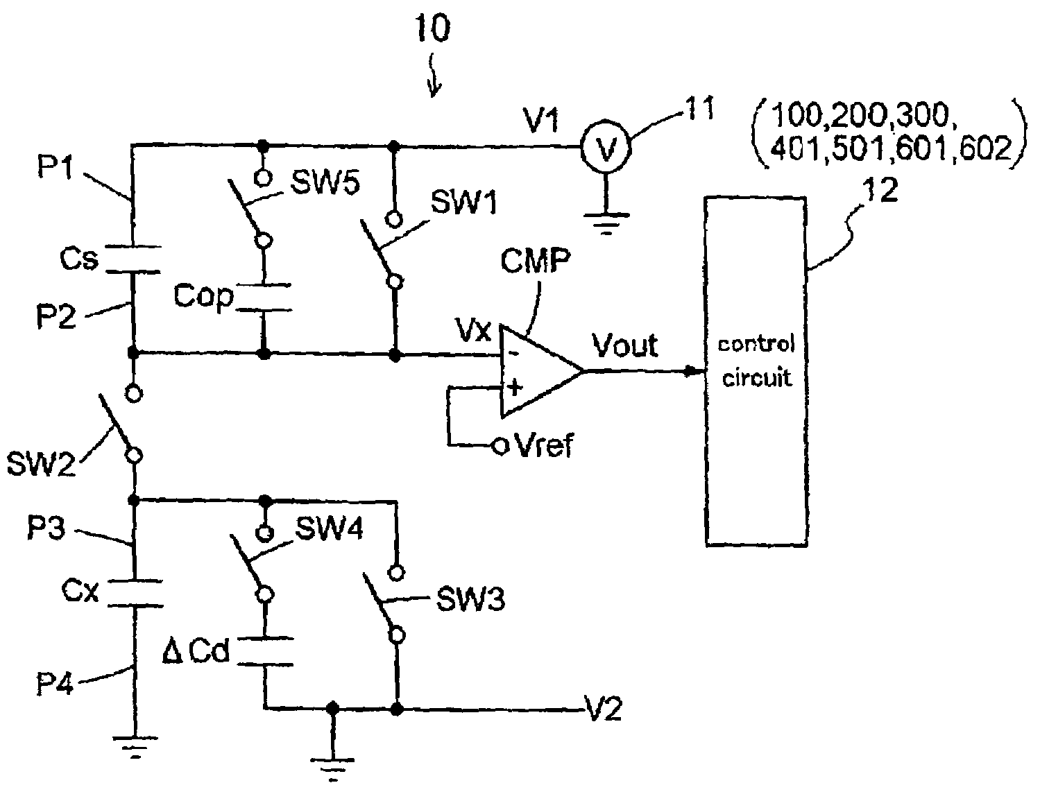
[0022]As shown in FIG. 1, a capacitance change measurement device (serving as a capacitance change detection device) includes a first opening and closing switch SW1 provided between ends P1, P2 of a reference capacitance Cs, a first electric potential source V1 connected to the first end P1 of the reference capacitance Cs, a second opening closing switch SW2 connecting the second end P2 of the reference capacitance Cs and a first end P3 of the sensor electrode capacitance Cx, a third opening and closing switch SW3 provided between the first end P3 and a second end P4 of the sensor electrode capacitance Cx, and a comparator CMP serving as an electric potential measurement means for measuring an electric potential Vx at the second end P2 of the reference capacitance Cs. The second end P4 of the sensor electric capacitance Cx is connected to a second electric poten...


PUM


Abstract

A capacitance change detection device includes a sensor electrode, and an electrode capacitance measurement device for measuring capacitance of the sensor electrode on the basis of a correlation value based on a reference capacitance at every first predetermined time. A detection signal is generated when a current measurement value of capacitance is changed by equal to or greater predetermined threshold value than a measurement value obtained a second predetermined time before the current measurement value is measured. The capacitance change detection device further includes a sensitivity compensation capacitance for generating capacitance variations equivalent to specific variations of capacitance of the sensor electrode, and being switched between a connected state and a disconnected state. The threshold value is determined as a difference between measurement values of capacitance of the sensor electrode measured at the connected state and at the disconnected state. The threshold value is renewed at every third predetermined time.

Description

CROSS REFERENCE TO RELATED APPLICATIONS[0001]This application is based on and claims priority under 35 U.S.C. §119 with respect to Japanese Patent Application NO. 2004-4098667 filed on Mar. 30, 2004, the entire content of which is incorporated herein by reference.FIELD OF THE INVENTION[0002]The present invention relates to a capacitance change detection device for detecting a change of capacitance.BACKGROUND[0003]Capacitance change detection devices are used for detecting a trigger for opening operation (i.e., unlock operation) of systems for controlling opening and closing of a vehicle door for such as automobiles. More particularly, when a mode of a device provided at a vehicle is switched to an unlock allowance mode because a user approaches the vehicle and a code is identified between the device provided at the vehicle and a remote controller carried by the user, and when the user further touches an unlock sensor (i.e., an electrode) provided inside of an outside handle of the v...

Claims


Application Information

Patent Timeline
Patent Type & Authority Patents(United States)
IPC IPC(8): G01R27/26E05B49/00B60R25/01B60R25/24G01D5/24G01V3/08H03K17/955
CPCG01D5/24H03K17/955G01R27/2605H03K2217/94031G01R27/26
Inventor INABA, HISASHIKURACHI, KOHEIHATANO, RIKUO
Owner AISIN SEIKI KK
Why Eureka
Try Eureka