Electromagnetic field communications system for wireless networks

a wireless network and electromagnetic field technology, applied in the direction of transmission, power distribution line transmission, broadcast with distribution, etc., can solve the problems of signal not easily passing through walls, dead spots, and hf band that has not been exploited in the past for communications networks

Inactive Publication Date: 2006-08-29
COCOMO MB COMM INC
View PDF14 Cites 38 Cited by
  • Summary
  • Abstract
  • Description
  • Claims
  • Application Information

AI Technical Summary

Benefits of technology

[0039]The selection of the High Frequency, Very High Frequency, and the lower end of the Ultra High Frequency bands offers two important advantages to the implementation of the invention. First, since most other radio services avoid these bands due to atmospheric and man-made noise, these frequencies are generally available for a revolutionary new service such as that offered by the present invention. Secondly, these frequency bands require large antennas. At 30 MHz, an appropriate conventional antenna size is 50 feet, while a 150 foot conventional antenna would be preferable for 10 MHz. These dimensions are well-suited for this frequency band. For a building which is 50 by 100 feet and 20 feet tall, the building is 0.2×1.0×0.2 wavelengths at 30 MHz, or 0.1×0.5×0.4 wavelengths at 15 MHz.

Problems solved by technology

The HF band has not been exploited in the past for communications networks because of problems stemming from 1) the high atmospheric and man made noise and 2) the large size of antennas for this region of the spectrum.
These bands are characterized by scatter and multi-path, which result in dead spots.
Furthermore, signals do not readily pass through walls, and are severely affected by the presence of personnel.

Method used


Image

  • Electromagnetic field communications system for wireless networks
  • Electromagnetic field communications system for wireless networks
  • Electromagnetic field communications system for wireless networks

Examples


Embodiment Construction

I. Electromagnetic Waves

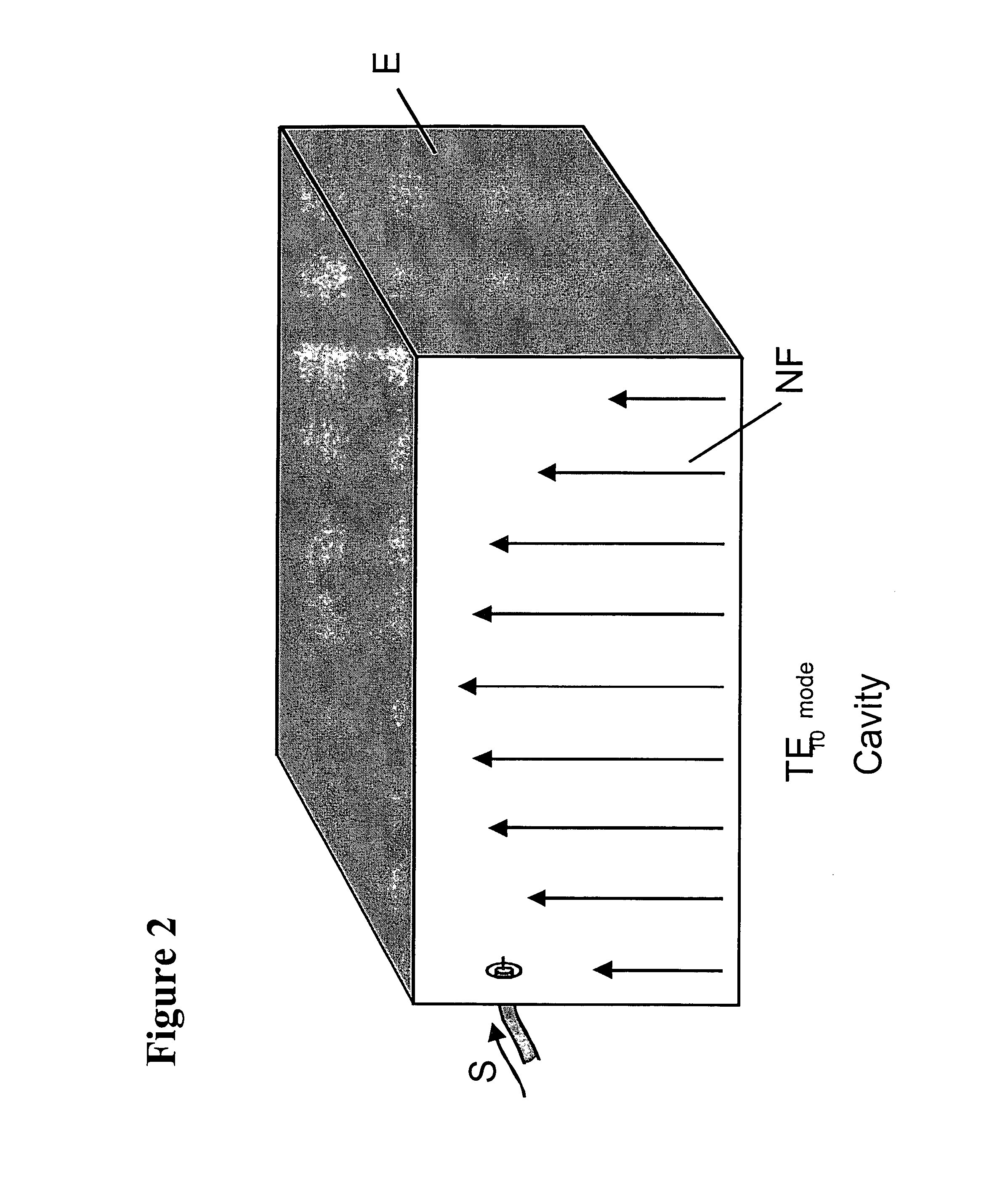
[0026]When radio frequency energy is coupled to a cavity, an electromagnetic field is created within the cavity. This cavity may be formed of solid metallic surfaces or a grid of wires. The coupler or exciter establishes currents in the walls which in turn establish an internal electromagnetic field. This field distribution is invariant with the magnitude of the voltage component of the field, varying only at the carrier rate of the exciting frequency.

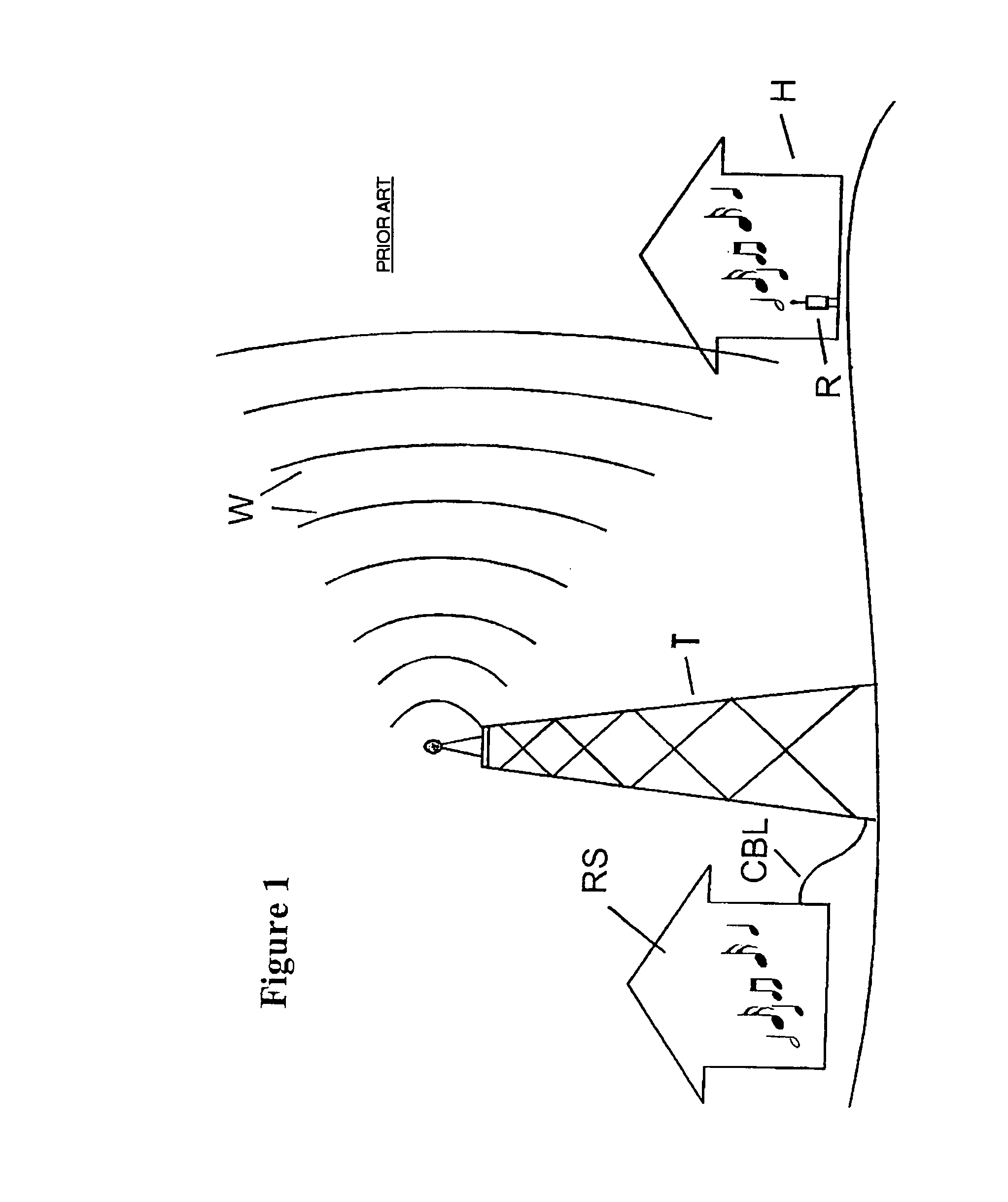
[0027]FIG. 1 supplies a simplified schematic illustration of a conventional radio station RS. Radio signals containing the information that will be broadcast to listeners are fed to a tall metal transmitting tower over a cable CBL. The tower is composed of conductive metal that creates a field of radio waves W. These fields propagate or travel great distances through the air until they reach a radio receiver R like the one pictured in the house H in FIG. 1. The radio R detects the signal, and converts it to audi...


PUM


Abstract

An Electromagnetic Field Communications System for Wireless Networks for producing an electromagnetic field within a structure is disclosed. The electromagnetic field is produced by using common conductive elements already present within virtually all pre-existing residential commercial, industrial buildings. These conductors, which may include electrical ground shields, wiring, pipes, sprinkler conduits or structural members, are excited with a signal, and become the cavity which contains the electromagnetic field. In preferred embodiments of the invention, signals are generated using the High Frequency, Very High Frequency and lower UHF bands (3 to 30, 30 to 300 and up to 400 MHz). The invention may be used to create a local area network inside the field and within the structure. Devices that include receivers tuned to the electromagnetic field may then be connected and networked. The system may be operated without causing interference to other conventional radio devices outside the structure in the HF band.

Description

FEDERALLY SPONSORED RESEARCH OR DEVELOPMENT[0001]None.FIELD OF THE INVENTION[0002]The present invention includes methods and apparatus for providing a wireless communications system. More particularly, the preferred embodiments of the invention utilize the High Frequency, Very High Frequency and the lower end of the Ultra High Frequency (HF, VHF & UHF) bands to generate electromagnetic fields within a building or structure. Conductors within the building or structure are used as an exciter to create a localized quasi-static electromagnetic field that may be used to connect a wide variety of devices without wires and without suffering undue interference from external noise.BACKGROUND OF THE INVENTION[0003]Over the past two decades, the meteoric rise of the personal computer has transformed the world. A recent report in Forbes notes that over 100 million personal computers were sold in 1998 alone. In just the past few years, the ability to connect all of these millions of computers di...

Claims


Application Information

Patent Timeline
Patent Type & Authority Patents(United States)
IPC IPC(8): H04H1/00H01Q1/44H01Q1/00H01Q1/22H01Q1/46H01Q1/52H04B3/54H04B5/00H04H20/00
CPCH01Q1/007H01Q1/22H01Q1/526H01Q1/46H01Q1/2208H01Q1/52
Inventor CHADWICK, GEORGE G.
Owner COCOMO MB COMM INC
Why Eureka
Try Eureka