Adjustable multi-band antenna

a multi-band antenna and adjustable technology, applied in the direction of resonant antennas, substation equipment, transmission, etc., can solve the problems of increasing the difficulty or the inability to cover the frequency range used by more than one radio system, the distance between the radiating plane and the ground plane of an internal planar antenna unavoidably becoming shorter, and the inability to match and improve the matching efficiency of the antenna

Inactive Publication Date: 2006-08-29
CANTOR FITZGERALD SECURITIES
View PDF9 Cites 65 Cited by
  • Summary
  • Abstract
  • Description
  • Claims
  • Application Information

AI Technical Summary

Benefits of technology

[0013]An advantage of the invention is that by controlling the switch only one operation band of the antenna is affected. This is due to that concerning other operation bands, because of the filter, a high impedance is seen from the parasitic element towards the ground it is “seen” a high impedance, although the switch would be closed. Another advantage of the invention is that closing the switch does not deteriorate the antenna's matching and efficiency in said other operation bands. A further advantage of the invention is that an advantageous place for the parasitic element can be searched more freely than without the filter. A further advantage of the invention is that the adjusting circuit can be designed more freely than without the filter. A further advantage of the invention is that possibility of electro-static discharges (ESD) through the switching circuit is lower.
is that by controlling the switch only one operation band of the antenna is affected. This is due to that concerning other operation bands, because of the filter, a high impedance is seen from the parasitic element towards the ground it is “seen” a high impedance, although the switch would be closed. Another advantage of the invention is that closing the switch does not deteriorate the antenna's matching and efficiency in said other operation bands. A further advantage of the invention is that an advantageous place for the parasitic element can be searched more freely than without the filter. A further advantage of the invention is that the adjusting circuit can be designed more freely than without the filter. A further advantage of the invention is that possibility of electro-static discharges (ESD) through the switching circuit is lower.

Problems solved by technology

As portable radio devices, like mobile terminals, are becoming smaller thickness-wise, too, the distance between the radiating plane and the ground plane of an internal planar antenna unavoidably becomes shorter.
A drawback of the reducing of said distance is that the bandwidths of the antenna are becoming smaller.
Then, as a mobile terminal is designed to function according to different radio systems having frequency ranges relatively close to each other, it becomes more difficult or impossible to cover said frequency ranges used by more than one radio system.
Correspondingly, securing the function that conforms to specifications in both transmitting and receiving bands of a single system can become more difficult.
A drawback of this solution is that it is designed only for a one-band antenna.
Moreover the structure comprises, compared with an usual PIFA, an additive short-circuit conductor with it's arrangements, resulting to extra manufacturing cost of the antenna.
That results in the electric length of the slot radiator shortening and the resonance frequency rising.
However a drawback is that directing the effect only to the higher operation band is not successful in the practice.
Another drawback is increasing of dissipations of signals in the lower band so that the antenna's efficiency in the lower band decreases e.g. from 0.5 to 0.4.

Method used


Image

  • Adjustable multi-band antenna
  • Adjustable multi-band antenna
  • Adjustable multi-band antenna

Examples


Embodiment Construction

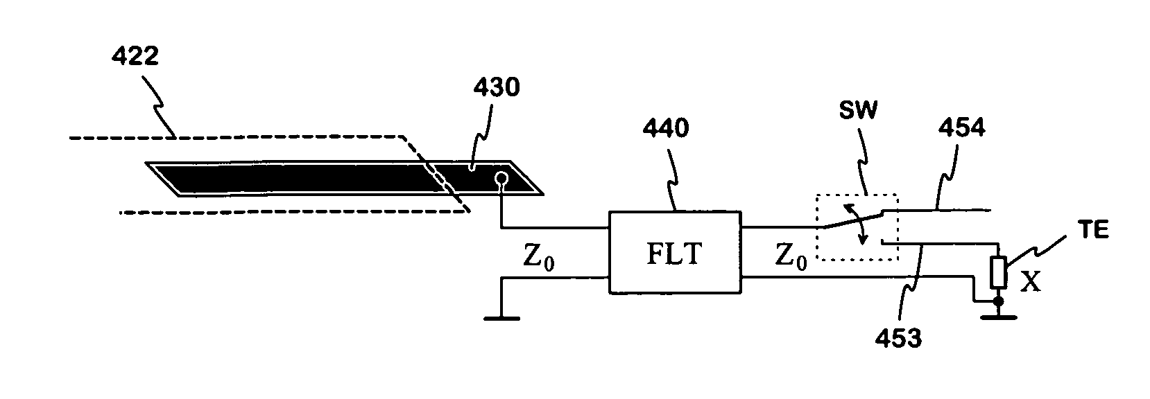
[0025]FIG. 4 presents a structure showing the principle of the invention. From the antenna's base structure it is drawn only a part 422 of the radiating plane. The antenna's structure comprises, in addition to the base structure, an adjusting circuit having a parasitic element 430, a filter 440, a switch SW and a terminal element TE. The parasitic element has a significant electromagnetic coupling with the radiating plane's part 422 and it is connected through a short transmission line to the input port of the filter 440. The output port of the filter is connected through a second short transmission line to the two-way switch SW, the “hot” terminal of the output port to the first terminal of the switch SW. The first terminal can be connected either to the second or to the third terminal of the switch by controlling the switch. The second terminal is fixedly connected to one conductor 453 of a third short transmission line. In the opposite end of the third transmission line is the te...


PUM


Abstract

An adjustable multi-band planar antenna especially applicable in mobile terminals. In the structure of the antenna, advantageously on a surface of a dielectric part, there is placed a conductive element (430) having a significant electromagnetic coupling to the radiating plane (422). The arrangement further comprises a filter (440) and a switch (SW) so that the parasitic conductive element at issue can be connected through the filter to a terminal element (TE) connected to the ground plane. That terminal element is pure short-circuit or a reactive element. An antenna's operation band, which is desired to be displaced, situates on pass band of the filter, and another operation band, which is desired not to be effected, situates in stop band of the filter. Controlling the switch causes the electric length of the antenna's part corresponding for example the upper operation band to change measured from the short-circuit point, in which case also the resonance frequency changes and the band is displaced. Only one operation band of the antenna is affected because on the other operation bands a high impedance is “seen” from the parasitic element towards the ground, although the switch is closed.

Description

[0001]The invention relates to an adjustable multi-band planar antenna especially applicable in mobile terminals. The invention further relates to a radio device equipped with that kind of antenna.BACKGROUND OF THE INVENTION[0002]The adjustability of an antenna means in this description, that a resonance frequency or frequencies of the antenna can be changed electrically. The aim is that the operation band of the antenna round a resonance frequency always covers the frequency range, which the function presumes at a given time. There are different grounds for the adjustability. As portable radio devices, like mobile terminals, are becoming smaller thickness-wise, too, the distance between the radiating plane and the ground plane of an internal planar antenna unavoidably becomes shorter. A drawback of the reducing of said distance is that the bandwidths of the antenna are becoming smaller. Then, as a mobile terminal is designed to function according to different radio systems having f...

Claims


Application Information

Patent Timeline
Patent Type & Authority Patents(United States)
IPC IPC(8): H04B1/38H01Q1/24H04M1/00H01Q5/10H01Q9/04H01Q21/30
CPCH01Q1/243H01Q21/30H01Q9/0442H01Q9/0421
Inventor MILOSAVLJEVIC, ZLATOLJUB
Owner CANTOR FITZGERALD SECURITIES
Why Eureka
Try Eureka