Method and device for simulation of a closing wedge

Inactive Publication Date: 2006-09-05
INOS AUTOMATIONSSOFTWARE
View PDF9 Cites 8 Cited by
  • Summary
  • Abstract
  • Description
  • Claims
  • Application Information

AI Technical Summary

Benefits of technology

[0020]To reduce the size and facilitate handling of the device, the pneumatic suctioning device and the mechanical stop are formed as a closing wedge simulation unit which can be pivoted about a common axis of rotation. The unit can be moved on a common handling device and be supported on the surrounding body or on i

Problems solved by technology

The insertion of the closing wedge is a very difficult and also very inaccurate procedure
The use of a magnet for closing wedge simulation is, ho

Method used


Image

  • Method and device for simulation of a closing wedge
  • Method and device for simulation of a closing wedge
  • Method and device for simulation of a closing wedge

Examples


Example

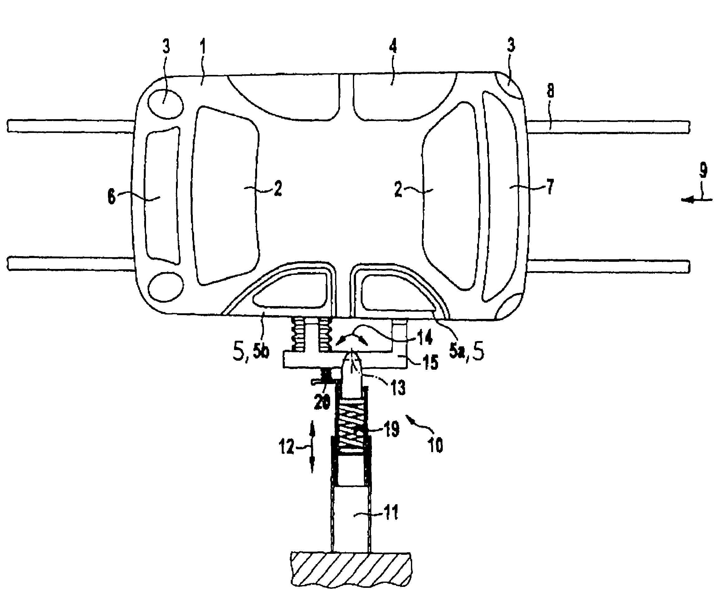
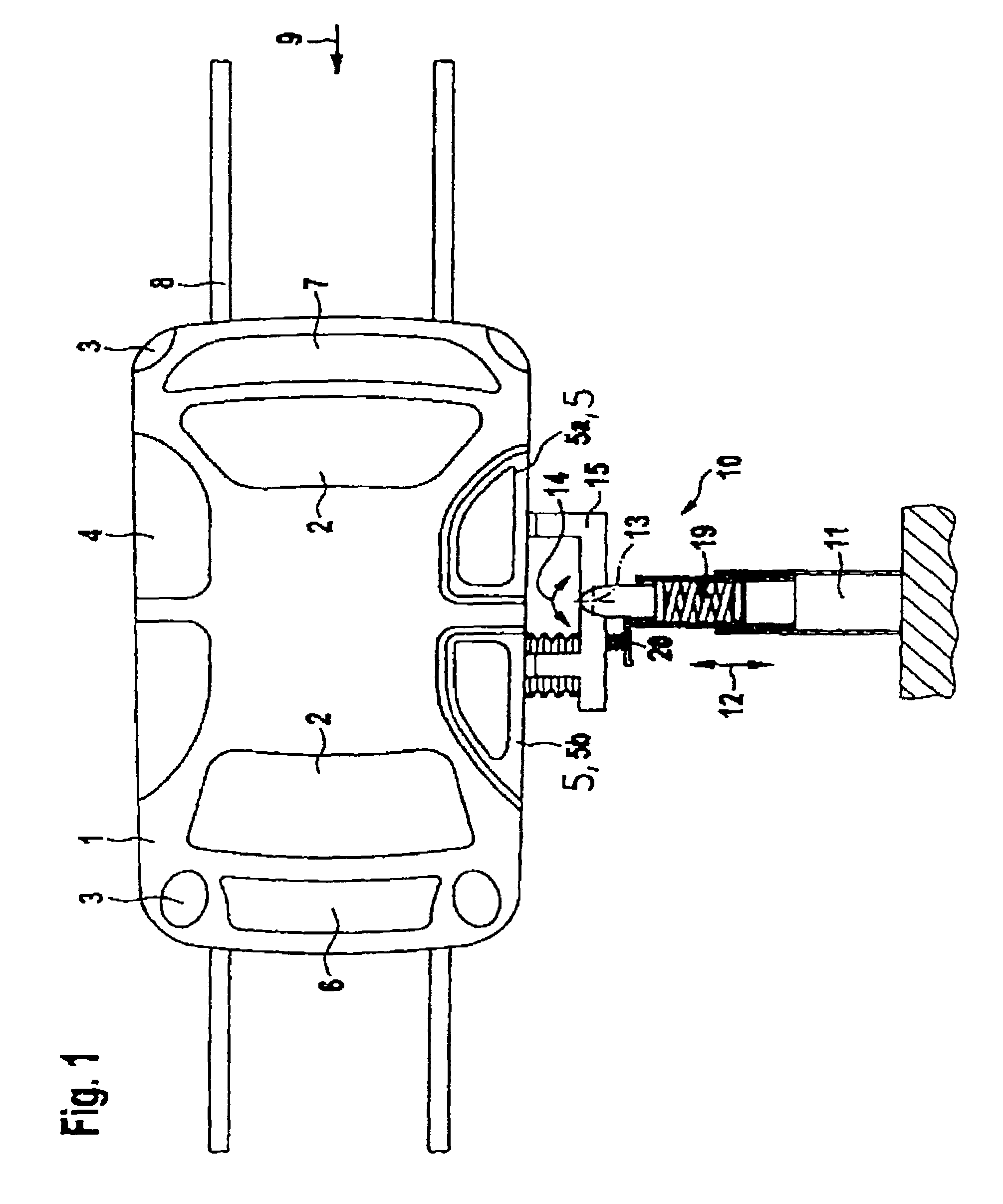
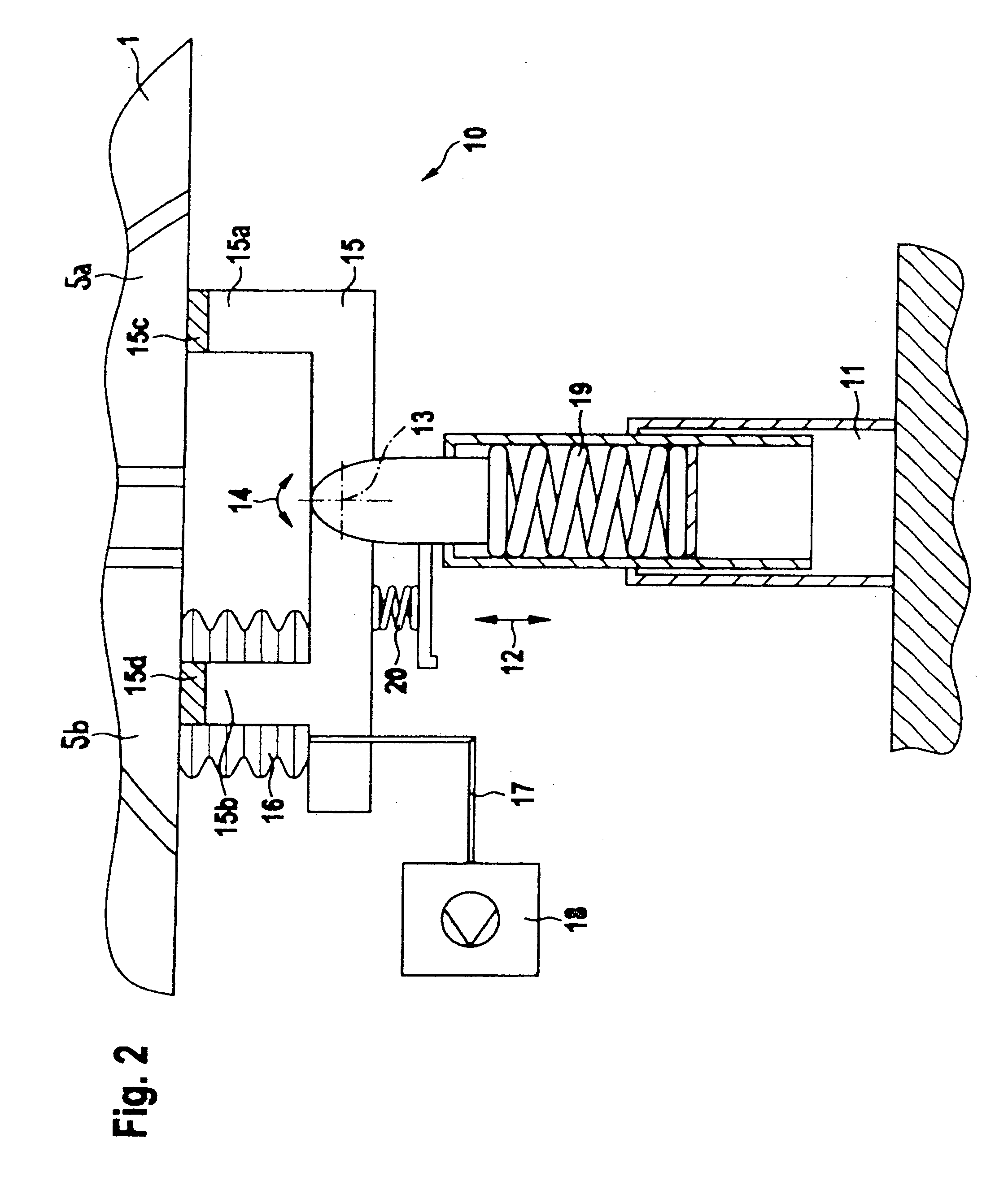
[0027]FIG. 1 shows a vehicle body designated as 1. The body 1 has installation openings 2 for windshield and rear window and installation openings 3 for headlamps and rear lamps. The body 1 also has installation openings 4 for doors 5, an installation opening 6 for a hood and an installation opening 7 for a trunk lid or a rear flap. The doors 5, the hood and the trunk lid or the rear flap are commonly referred to as flaps.

[0028]The body is moved on an assembly line 21 (FIG. 3) past different mounting stations, i.a. also past a station (shown in FIG. 1) for installing the flaps 5. The assembly line 21 may be formed as an unguided transport system (UTS) or in any other form. In particular, the body 1 can be mounted to the assembly line 21 or be suspended from the assembly line. In the present embodiment of FIG. 1, the assembly line 21 is formed as an UTS on which the body 1 is mounted and which moves along a predetermined path in the direction of an arrow 9 by means of guiding rails o...


PUM

PropertyMeasurementUnit
Timeaaaaaaaaaa
Dimensionaaaaaaaaaa
Surfaceaaaaaaaaaa

Abstract

The invention concerns a method and a device (10) for closing wedge simulation to set gap dimensions between a movable flap (5; 5a, 5b) of a vehicle and the surrounding body (1) of the vehicle. The flap (5; 5a, 5b) is initially fitted and held in a roughly adjusted installation position in alignment with the body (1). The flap (5; 5a, 5b) is then finely adjusted such that predeterminable gap dimensions can be met with optimum precision. Finally, the flap (5; 5a, 5b) is movably fixed in the finely adjusted installation position on the body (1). To simplify the closing wedge simulation without losing accuracy for fine adjustment of the flap (5; 5a, 5b), the invention proposes to suction the flap (5; 5a, 5b) against a mechanical stop (15) for fine adjustment using a pneumatic suctioning device (16), wherein the mechanical stop (15) is fixed relative to the surrounding body (1) and is freely pivotable about a substantially vertical axis of rotation (13).

Description

[0001]This application is a continuation of PCT / EP03 / 12218 filed on Nov. 03, 2003 and claims Paris Convention priority of DE 102 51 393.7 filed Nov. 05, 2002 the entire disclosures of which are hereby incorporated by reference.BACKGROUND OF THE INVENTION[0002]The present invention concerns a method for setting the gap dimensions between a movable flap of an automotive vehicle and the adjacent body of the vehicle. In this method, the flap is initially fitted and held in a roughly adjusted installation position in alignment with the body, then finely adjusted such that predetermined gap dimensions can be established with maximum precision, and finally movably fixed in the finely adjusted installation position on the body.[0003]The invention also concerns a device for setting the gap dimensions between a movable flap of a vehicle and the adjacent body of the vehicle. The device comprises means for fitting and holding the flap in a roughly adjusted installation position in alignment wit...

Claims


Application Information

Patent Timeline
IPC IPC(8): B23Q7/00B23Q7/04B25B11/00B23Q3/00B25B27/14B62D65/06
CPCB62D65/06Y10S269/905Y10S269/909Y10T29/49998Y10T29/53974Y10T29/53991Y10T29/4978Y10T29/49902
Inventor TASSAKOS, CHARALAMBOSMETGE, JAN-THOMAS
Owner INOS AUTOMATIONSSOFTWARE
Why Eureka
Try Eureka