Method of installing double flanged bushings

a technology of tubular bushings and flanges, which is applied in the direction of multi-purpose tools, manufacturing tools, mechanical equipment, etc., can solve the problems of face-to-face contact between the joined parts, see an axial load,

Inactive Publication Date: 2006-09-05
FATIGUE TECH
View PDF32 Cites 63 Cited by
  • Summary
  • Abstract
  • Description
  • Claims
  • Application Information

AI Technical Summary

Benefits of technology

[0018]According to another aspect of the invention, a first bushing part is provided that has a tubular section and a radial flange section at one end of its tubular section. The tubular section of the first bushing part is provided with an outside diameter substantially corresponding to the diameter of the opening in the work member. The second bushing part is provided that has a tubular section and a radial flange section at one end of its tubular section. The tubular section of the second bushing part is provided with an outside diameter substantially corresponding to the inside diameter of the tubular section of the first bushing part. The tubular section of the first bushing part is moved into and through the opening in the work member, from the first side of the work member. It is moved axially until its flange section is substantially against the first side of the work member. Then, the tubular section of the second bushing part is inserted into the tubular section of the first bushing part, from the second side of the work member. The second bushing part is then moved axially to place its flange section substantially against the second side of the work member. The tubular sections of the first and second bushing parts are radially and circumferentially expanded together, an amount sufficient to provide a tight interference fit of the tubular section of the second bushing part in the tubular section of the first bushing part, and a tight interference fit of the tubular section of the first bushing part in the opening in the work member. They also may be radially and circumferentially expanded an amount sufficient to also introduce fatigue life enhancing compressive residual stresses in the work member immediately around the opening in the work member.
[0019]According to a further aspect of the invention, a first bushing part is provided that has a tubular section and a radial flange at one end of the tubular section. The tubular section has an outside diameter substantially corresponding to the diameter of the opening in the work member and a length that is only a portion of the length of the opening in the work member. A second bushing part is provided that has a tubular section and a radial flange at one end of the tubular section. This tubular section also has an outside diameter substantially corresponding to the diameter of the opening in the work member and a length that is less than the length of the opening in the work member. The tubular section of the first bushing part is inserted into the opening in the work member, from the first side of the work member, and is moved axially to place the flange section of the first bushing part against the first side of the work member. The tubular section of the second bushing part is inserted into the opening in the work member, from the second side of the work member, and is moved axially until the flange section of the second bushing part is against the second side of the work member. Then, the two tubular sections are radially and circumferentially expanded an amount sufficient to provide a tight interference fit between them and the opening in the work member, for connecting the first and second bushing parts to the work member. The cold expansion may also be sufficient to introduce fatigue life enhancing compressive residual stresses in the work member immediately around a through opening in the work member.
[0020]According to yet another aspect of the invention, a tubular first bushing part is provided that has an outside diameter substantially corresponding to the diameter of the opening in the work member and a length substantially corresponding to the length of the opening in the work member. A second bushing part is provided that has a tubular section and a radial flange section at one end of the tubular section. The tubular section of the second bushing part has an outside diameter substantially corresponding to the inside diameter of the first bushing part and a length that is a portion of the length of the first bushing part. A third bushing part is provided. It has a tubular section and a radial flange section at one end of the tubular section. The tubular section of the third bushing part also has an outside diameter substantially conforming to the inside diameter of the first bushing part and a length that is a portion of the length of the first bushing part. The first bushing part is inserted into the opening in the work member. Then, the tubular section of the second bushing part is inserted into the first bushing part, from the first side of the work member. The second bushing part is moved axially until its flange section is against the first side of the work member. Next, the tubular section of the third bushing part is inserted into the first bushing part, from the second side of the work member. The third bushing part is moved axially until its flange section is against the second side of the work member. Then, the first bushing part and the tubular sections of the second and third bushing parts are radially expanded together an amount sufficient to provide a tight interference fit between the first bushing part and the opening in the work member and between the tubular sections of the second and third bushing parts and the first bushing part. The bushing parts are expanded circumferentially an amount sufficient to connect the second and third bushing parts to the first bushing part and connect the first bushing part to the work member. They also may be radially expanded an amount sufficient to introduce fatigue life enhancing compressive residual stresses in the work member substantially surrounding the through opening in the work member.

Problems solved by technology

For example, when bushings are used in a lug or clevis, there is a potential of face-to-face contact between the joined parts.
However, it could also see an axial load due to the fore and aft loading of the lug.

Method used


Image

  • Method of installing double flanged bushings
  • Method of installing double flanged bushings
  • Method of installing double flanged bushings

Examples


first embodiment

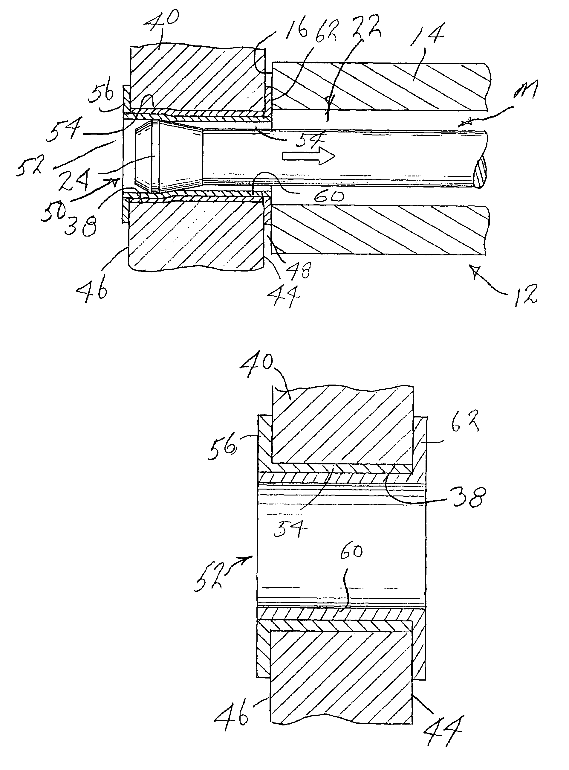
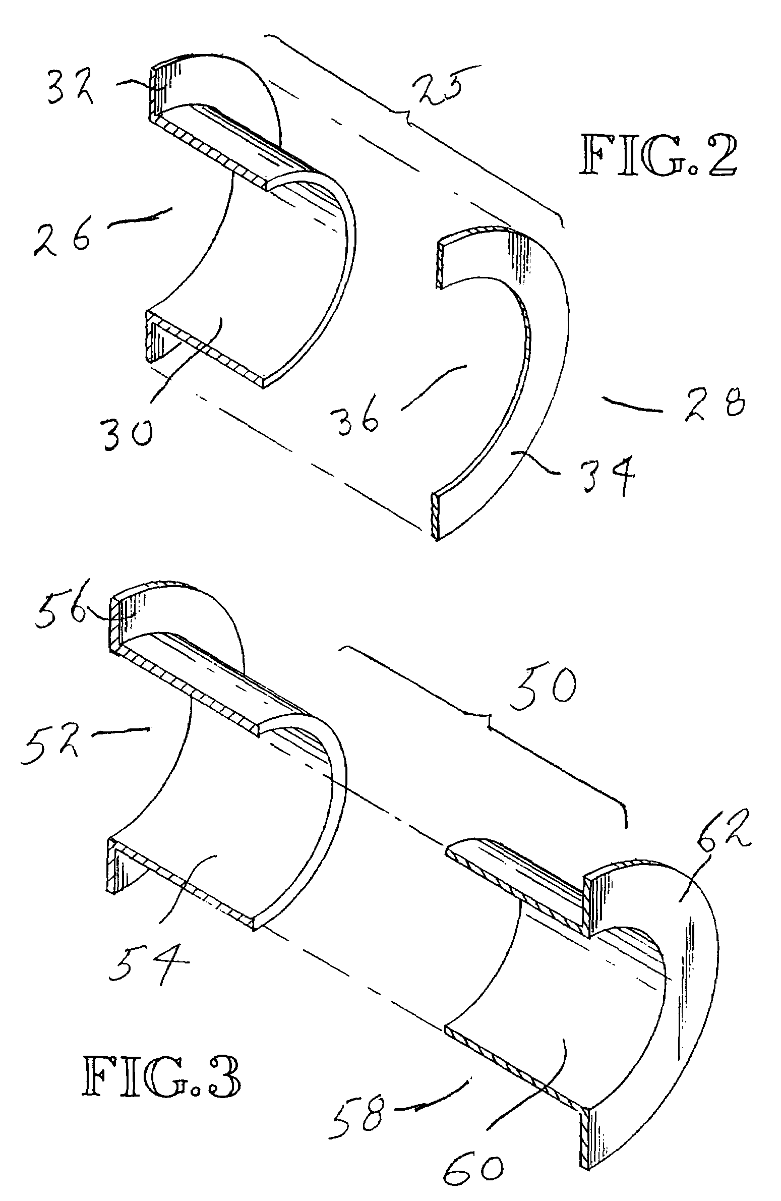
[0041]FIGS. 2, 6–8 and 12 disclose the double flanged bushings of the present invention. This bushing 25 is composed of a first bushing part 26 and a second bushing part 28. Bushing part 26 comprises a tubular section 30 and a radial flange section 32. Flange section 32 is connected to one end of the tubular section 30. Tubular section 26 extends axially and radial flange section 32 extends radially. Bushing part 28 is a radial member 34 that includes a center opening 36. Preferably, but not necessarily, the radial length of member 34 substantially equals the radial length of flange section 32 measured from the outside diameter of the tubular section 30.

[0042]A through opening 38 is provided in a work member 40 to receive the bushing 25. An initial opening 38 is formed by use of a drill. The drilled opening is then reamed to provide a desired starting diameter. After reaming, the starting diameter is verified by use of a hole-diameter gauge. If the opening 38 is oversized, it must b...

third embodiment

[0051]FIGS. 4, 10 and 14 disclose the bushing. This bushing 66 has three parts. A tubular first bushing part 68 has an outside diameter and a length that correspond to the diameter and length of opening 38 in work member 40. The second bushing part 70 has a tubular section 72 and a radial flange section 74 at one end of the tubular section 72. It has an outside diameter substantially conforming to the inside diameter of bushing part 68. It has a length that is shorter than the opening 38 in work member 40. The third bushing part 76 has a tubular section 78 and a radial flange section 80 at one end of the tubular section 78. Preferably, bushing parts 70, 76 are alike. Preferably also, the tubular sections 72, 78 are substantially the length of tubular section 68 and the opening 38 in the work member 40.

[0052]Bushing 66 is installed in the following manner. Firstly, bushing part 68 is placed in the opening 38 in work member 40. Then, tubular section 72 of bushing part 70 is inserted i...

fourth embodiment

[0053]FIGS. 5, 8 and 15 show the bushing. This bushing 86 is composed of two bushing parts 88, 90 which are preferably identical in construction. Bushing part 88 has a tubular section 92 and a radial flange section 94 that is connected to one end of the tubular section 92. Bushing part 90 has a tubular section 96 and a radial flange section 98 that is connected to one end of the tubular section 96. The outside diameters of the tubular sections 92, 98 substantially conform to the diameter of the opening 38 in the work member 40. The tubular sections 92, 96 are both shorter than the opening 38 but, preferably, their combined lengths substantially equal the length of the opening 38 (FIG. 15). The tubular sections 92, 96 may have concentric end portions that form a lap joint where they meet. End part 92′ concentrically surrounds end part 96′.

[0054]The bushing 86 is installed in the following manner. The tubular sections 92, 96 are either installed separately or together into the opening...


PUM

PropertyMeasurementUnit
outer circumferenceaaaaaaaaaa
circumferenceaaaaaaaaaa
compressive residual stressesaaaaaaaaaa

Abstract

A bushing (52) has two bushing parts (52, 58), each of which includes a tubular section (54, 60) and a radial flange section (56, 62) Tubular section (54) is inserted into an opening (38) in a work member (40), from one side of the work member (40). Tubular section (60) is inserted into tubular section (54) from the opposite side (44) of the work member (40). A mandrel (M) is moved through the interior of the tubular portion of the bushing to radially and circumferentially expand the tubular portion of the bushing and move the flange sections against the opposite sidewalls of the work member (40). The tubular portions (54, 60) of the bushing (52) is radially and circumferentially expanded an amount sufficient to introduce fatigue life enhancing compressive residual stresses in the work member (40) immediately around the opening (38) in the work member (40).

Description

RELATED APPLICATION[0001]This application is a divisional of U.S. Ser. No. 09 / 603,857, filed Jun. 26, 2000, and entitled Double Flanged Bushings and Installation Methods.TECHNICAL FIELD[0002]The present invention relates to the provision and installation of tubular bushings in openings in work members. More particularly, it relates to the provision of bushings having flanges at both ends and to methods of radially expanding tubular portions of the bushings to create a tight interference fit between them and the openings in the work member.BACKGROUND OF THE INVENTION[0003]It is known to secure a bushing within an opening in a structural wall by positioning the bushing within the opening, holding it in place, and then forcing an expansion mandrel through the bushing to radially expand the bushing into an interference fit with the opening.[0004]U.S. Pat. No. 4,809,420, granted Mar. 7, 1989, to Michael A. Landy, Todd L. Thompson and Larry I. Wiemann, and U.S. Pat. No. 5,433,100, granted...

Claims


Application Information

Patent Timeline
Patent Type & Authority Patents(United States)
IPC IPC(8): B21D39/00B23P9/02F16B4/00
CPCB23P9/025F16B4/004Y10T16/05Y10T16/063Y10T403/4991Y10T403/4924Y10T29/4992Y10T29/49863Y10T29/4994Y10T29/49945Y10T29/49911Y10T29/49938
Inventor SKINNER, WILLIAM A.RESTIS, JUDE H.WEISS, MARK R.
Owner FATIGUE TECH
Why Eureka
Try Eureka