
Irregular and normal outer chain board mixing assembling device

A technology of mixed assembly and outer chain plate, applied in the direction of metal chains, etc., can solve the problems of easy failure, many links, precision control and processing speed limit, etc., to achieve convenient assembly and control, simple control structure and strong stability Effect

Pending Publication Date: 2018-12-25
浙江象牌链传动有限公司
View PDF0 Cites 0 Cited by
  • Summary
  • Abstract
  • Description
  • Claims
  • Application Information

AI Technical Summary

Problems solved by technology

The chain components are all assembled on the same equipment, which makes the equipment complex, with many links and prone to failure
The existing chain assembly equipment has relatively large limitations on precision control and processing speed, which seriously affects the chain production speed and assembly quality
Moreover, the chain assembly model is single, and it is impossible to assemble the special-shaped upper and lower chain plates, which has great limitations

Method used


Image

  • Irregular and normal outer chain board mixing assembling device
  • Irregular and normal outer chain board mixing assembling device
  • Irregular and normal outer chain board mixing assembling device

Examples


Embodiment 2

[0091] The difference between this embodiment and Embodiment 1 is that the slider blocking mechanism includes a slider switch part 125 fixed on one side of the slider fixed mold 1, and the slider switch part 125 is pivotally connected to the first slider 2 On the slider fixed mold 1 between the second slider 3, a torsion spring 126 is provided on the pivot shaft of the slider switch part 125, and the torsion spring 126 provides locking for the slider switch part 125. One side of the slider switch 125 is provided with a switch driver 121 , and the switch driver 121 drives the side of the slider switch 125 to overcome the force of the torsion spring 126 to lock and slide the second slider 3 .

[0092] The first slider 2 and the second slider 3 are respectively provided with corresponding grooves or stop protrusions 124 . The groove or the stopper protrusion 124 is in contact with the locking end 122 at both ends of the slider switch part 125, and the deadlock end 122 and the gro...

Embodiment 3

[0094] The difference between this embodiment and Embodiment 1 is that the first slider 2 and the second slider 3 are respectively provided with drive cylinders A131 on the opposite ends of the first lower chain push plate 2A and the second lower chain push plate 3A. and drive cylinder B132, the drive cylinder A131 and the drive cylinder B132 drive the slider to reciprocate, and a shaft hole is provided between the ends of the first lower chain plate push plate 2A and the second lower chain plate push plate 3A Connected to the rotatable triangular block 133 of the slider fixed mold 1, the triangular block 133, the distance between any corner of the triangular block 133 and the side corresponding to the corner is greater than that of the first lower chain plate push plate 2A and the second lower chain plate The distance from the opposite surface of the push plate 3A, the distance from the center of the shaft hole connection of the triangular block 133 to any side is smaller than...


PUM


Abstract

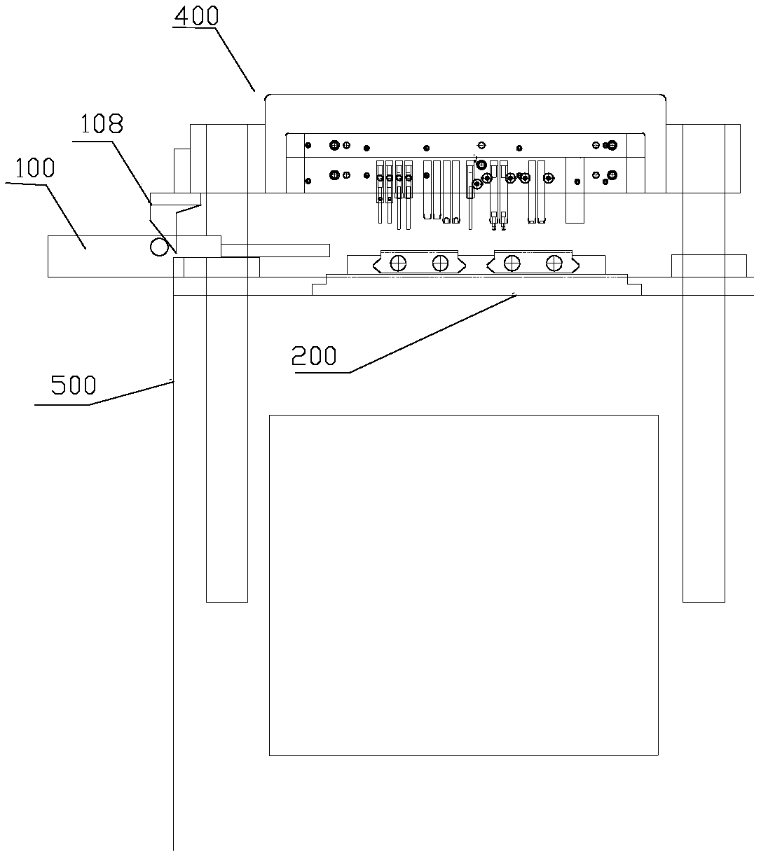
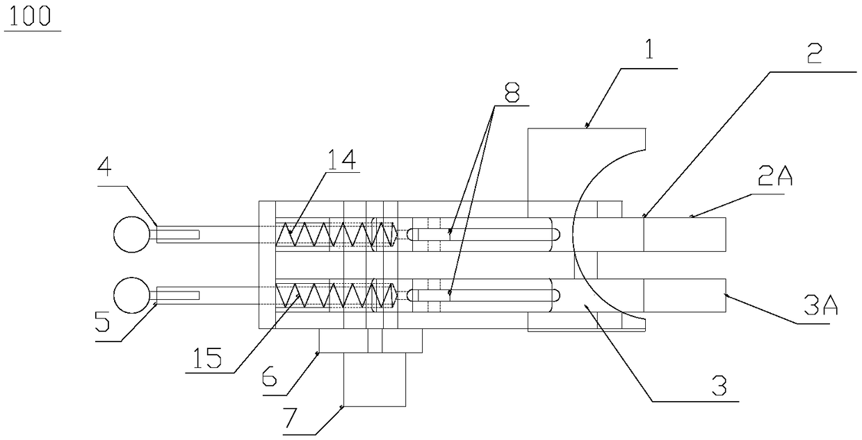
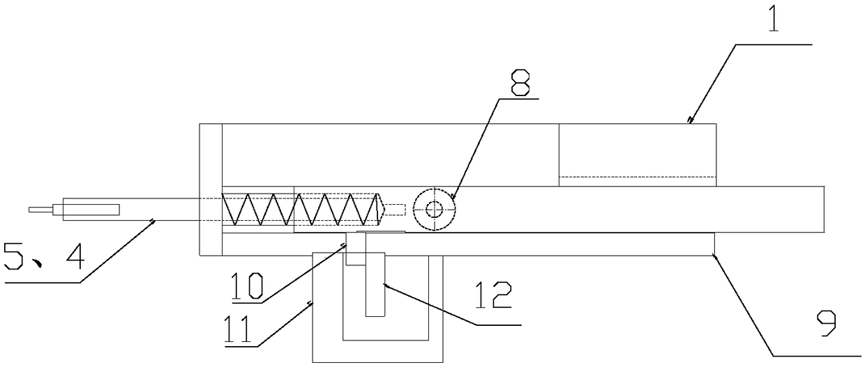
The invention relates to the technical field of chain assembling equipment, specifically to an irregular and normal outer chain board mixing assembling device. The device comprises a working platform,wherein an assembling groove and a pressing nail cross beam are mounted on the working platform, and the pressing nail cross beam can move up and down relative to the assembling groove; an assemblingpressing pin is arranged on the pressing nail cross beam; a lateral pushing plate is arranged on one side of the assembling groove, and a positioning sliding block is arranged on the other side of the assembling groove; a lower chain board pushing mechanism is arranged at one end of the working platform. According to the device, the lower chain board pushing mechanism is arranged at one end of the working platform; a lower chain board is assembled for a chain as required; a first sliding block or a second sliding block slides to push out different lower chain boards, and thus the lower chainboard of the chain can be a general chain board or an irregular chain board or be formed by alternatively connecting general chain boards and irregular chain boards.

Description

technical field [0001] The invention relates to the technical field of chain assembly equipment, in particular to a hybrid assembly equipment for special-shaped and conventional outer chain plates. Background technique [0002] A conventional roller chain consists of five parts: an inner chain plate, an outer chain plate, a pin shaft, a sleeve and a roller. The inner chain plate and the sleeve, the outer chain plate including the upper and lower chain plates and the pin shaft are all interference fits, and the sleeve and the pin shaft are clearance fit to form a dynamic connection. During operation, the inner and outer chain links can be relatively deflected, and the sleeve can rotate freely around the pin shaft. Both the inner and outer chain plates are made into an 8 shape, so that the tensile strength of each cross-section of the chain plates is roughly the same, and the weight and inertial force of the chain are reduced. [0003] The existing chain assembly equipment i...

Claims


Application Information

Patent Timeline
Patent Type & Authority Applications(China)
IPC IPC(8): B21L9/06
CPCB21L9/065
Inventor 徐志皓
Owner 浙江象牌链传动有限公司
Learn More