
Production method for motor and motor assembly

A manufacturing method and component technology, applied in the field of motor assembly and motor manufacturing, can solve problems affecting motor yield, assembly deviation, difficult positioning of motor components, etc., so as to avoid inaccurate positioning, improve yield, and fix firmly Effect

Active Publication Date: 2018-03-13
SHENZHEN EVERWIN PRECISION TECH
View PDF6 Cites 0 Cited by
  • Summary
  • Abstract
  • Description
  • Claims
  • Application Information

AI Technical Summary

Problems solved by technology

[0003] In the process of realizing the present invention, the inventor found that the related technology has the following problems: because the volume of the motor is very large, and the volume of the parts in the motor is smaller, it is difficult to position the parts of the motor when the motor is assembled manually, which is easy to cause Assembly deviations affect the yield of the motor

Method used

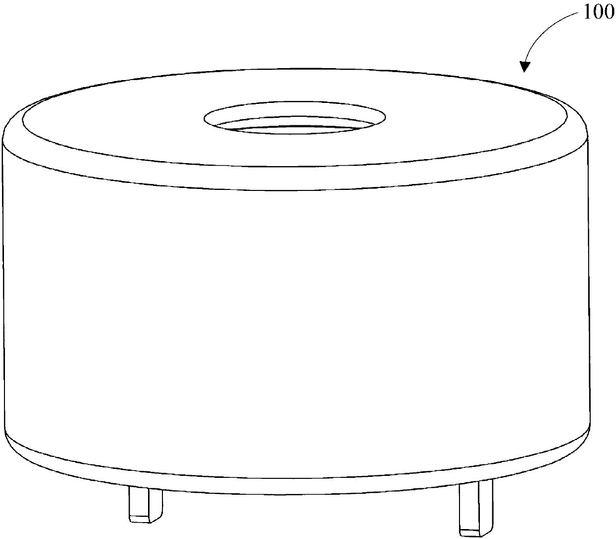
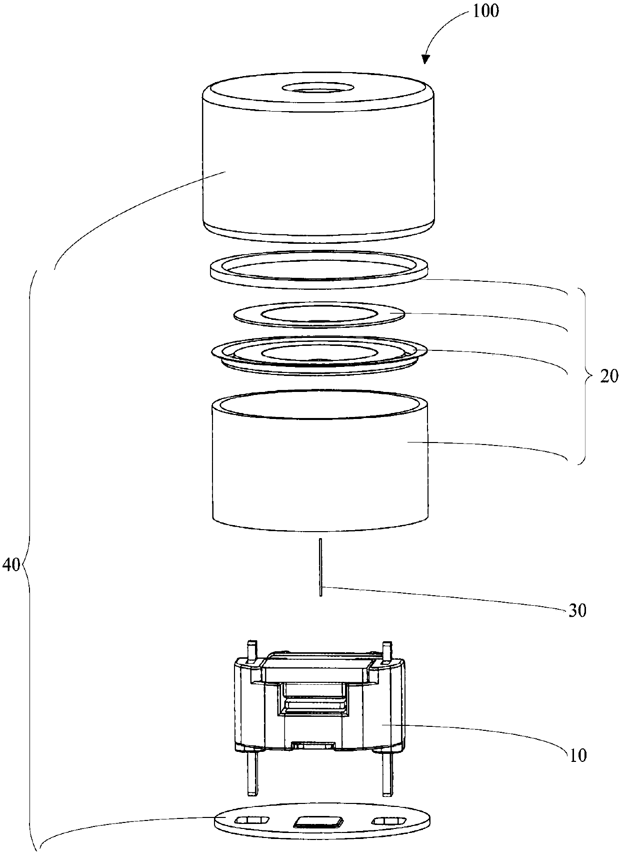

Image

  • Production method for motor and motor assembly
  • Production method for motor and motor assembly
  • Production method for motor and motor assembly

Examples


Embodiment 1

[0057] In order to improve the yield rate of the motor in the manufacturing of the above-mentioned moving iron unit, the present invention provides a method for producing the above-mentioned motor.

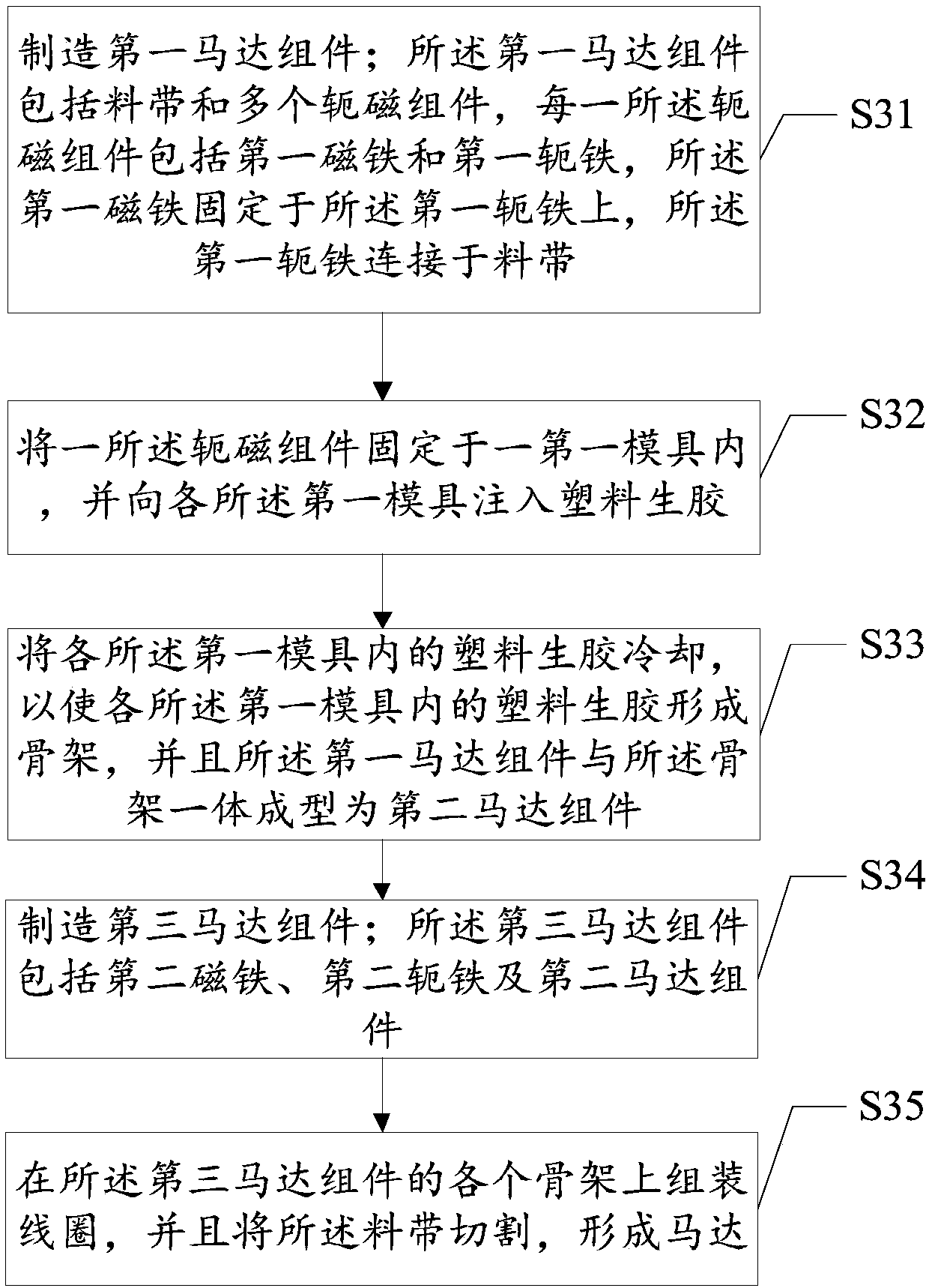
[0058] See image 3 , image 3 It is a schematic flowchart of a method for manufacturing a motor provided by an embodiment of the present invention, including:

[0059] Step S31: Manufacturing a first motor assembly; the first motor assembly includes a material tape and a plurality of yoke magnetic assemblies (not labeled), each of the yoke magnetic assemblies includes a first magnet and a first yoke, the first The magnet is fixed on the first yoke, and the first yoke is connected to the material belt;

[0060] Specifically, the first motor assembly such as Figure 4 Shown. The manufacturing process of the first motor assembly includes:

[0061] First fix the strip-shaped blanks on the assembly line by clamps. The strip-shaped blanks include a plurality of blank units. Each of the blank ...

Embodiment 2

[0086] See Figure 7 , The motor assembly 50 includes a first magnet 51, a first yoke 52, a frame 53, a lead wire outlet 54 and a material belt 55.

[0087] The number of the frame 53, the first yoke 53 and the first magnet 52 are multiple, and one of the first yoke 53 and one of the first magnets 51 are fixed, and the first yoke 52 is fixed to one of the first magnets 51. The frame 53 is fixed, and each first yoke 53 is connected to the material belt 55.

[0088] The material belt 55 is provided with a first positioning hole 551 and a second positioning hole 552. See Figure 8 The above-mentioned first magnet 51 has a rectangular parallelepiped structure, but may also be a cube structure or other three-dimensional structure that satisfies the fixation of the first magnet 51 to the first yoke 52.

[0089] See Picture 9 The above-mentioned first yoke 52 includes a yoke body 521, a first yoke arm 522, and a second yoke arm 523. The first yoke 52 has a U-shaped structure, and the firs...


PUM


Abstract

The embodiment of the invention relates to the field of balanced armature design and discloses a production method for a motor and a motor assembly. The method comprises the steps of producing a yokeiron assembly, wherein the yoke iron assembly comprises a strip and a plurality of pieces of first yoke irons, each piece of the first yoke iron is connected with the strip, a piece of first magnet iswelded on each piece of the first yoke iron, the piece of first magnet and each piece of the first yoke iron form a yoke magnet assembly, and all yoke magnet assemblies and the strip form a first motor assembly; forming skeletons on the yoke magnet assemblies of the first motor assembly to obtain a second motor assembly, assembling second magnet and second yoke iron on the second motor assembly to obtain a third motor assembly; assembling coils on the skeletons of the third motor assembly, and cutting the strip to obtain a plurality of motors. In the mode, the yield of the motors can be realized.

Description

Technical field [0001] The embodiment of the present invention relates to the field of moving iron design, in particular to a method of manufacturing a motor and a motor assembly. Background technique [0002] Moving iron units are widely used in moving iron earphones, hearing aids and other fields. In the moving iron unit, the motor is a very important component, which is equivalent to the engine of the moving iron unit. In the traditional motor assembly process, the main manual method is to fix the magnet and the yoke on the plastic sheet. The size of the plastic sheet ensures the consistency of the assembly, and the glue is cured by a UV oven or oven through the glue, so that the magnet and the yoke are fixed and combined. [0003] In the process of implementing the present invention, the inventor found that the related technology has the following problems: Because the size of the motor is very large, and the volume of the components in the motor is smaller, it is difficult to...

Claims


Application Information

Patent Timeline
Patent Type & Authority Applications(China)
IPC IPC(8): H04R31/00
CPCH04R31/00H04R2231/00Y02T10/64
Inventor 陈斌
Owner SHENZHEN EVERWIN PRECISION TECH
Learn More