High efficiency tank type continuous flow and self cleaning water heater

a self-cleaning, tank-type technology, applied in water heaters, furnace-tube steam boilers, lighting and heating apparatuses, etc., can solve the problems of overheating and damage of the coil, and the prior art also teaches the self-cleaning mechanism of the tank and the coil used by the system, so as to prevent overheating of the system and reduce condensation

Inactive Publication Date: 2006-09-05
FRASURE CHARLES J +3
View PDF7 Cites 16 Cited by
  • Summary
  • Abstract
  • Description
  • Claims
  • Application Information

AI Technical Summary

Benefits of technology

[0010]A specific object of the present invention is to reduce condensation in the coil and the flue pipe.
[0011]Another object is to provide means to prevent overheating of the system.
[0012]Another object of one embodiment of the present invention is to provide means for instant and continuous flow of hot water.
[0014]It has been found that improvements can be made to water heaters, such as providing an increase in the efficiency of heating, providing a continuous supply of water, and providing self cleaning of the water heater, and that these improvements can be obtained by using principle of conservation of heat energy by several means, and with the use of attachments.

Problems solved by technology

As a result, the coil can become overheated and get damaged when the burner is operating.
None of the aforesaid prior arts teaches for increasing the efficiency by controlling the condensation problem.
Moreover none of the prior arts also teaches a self-cleaning mechanism of tank and the coils used by the system.
Hence, the prior art devices do-not appear to substantially use the waste heat energy and prevent the accumulation of the sediments, despite claims to the contrary.

Method used


Image

  • High efficiency tank type continuous flow and self cleaning water heater
  • High efficiency tank type continuous flow and self cleaning water heater
  • High efficiency tank type continuous flow and self cleaning water heater

Examples


Embodiment Construction

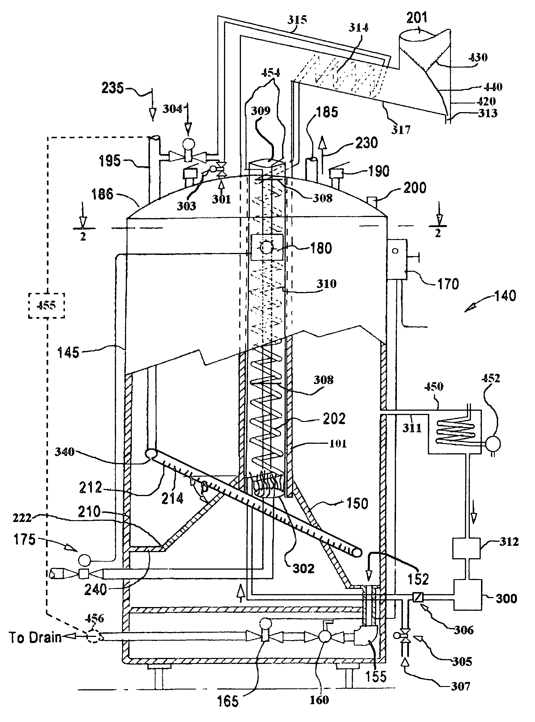
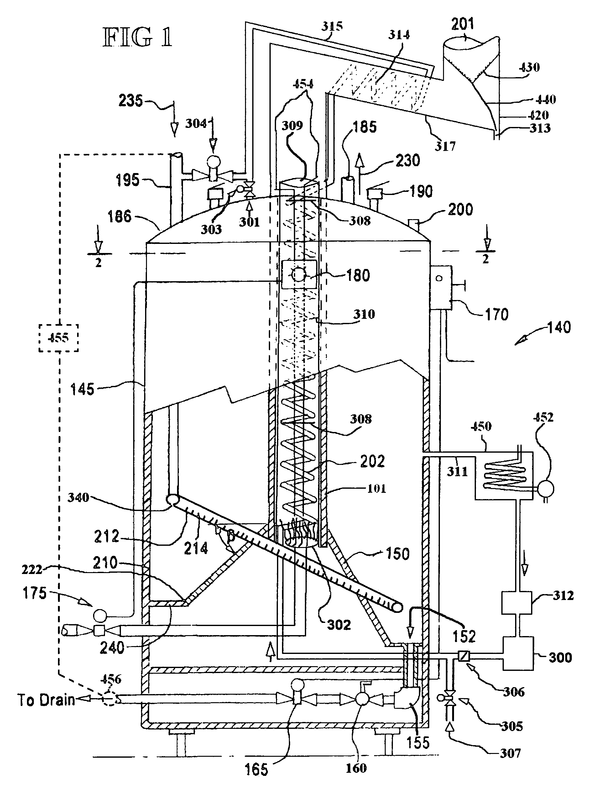
[0018]With reference to FIGS. 1 and 2, the water heater of the present invention comprises a a tank 140 having a water inlet 235 for connection with a water supply, and a hot water outlet 307 connected with the tank interior. A flue pipe 101 extends vertically through the tank and has an upper portion for connection with a vent pipe 201. A cylinder 309 having a lower end and an upper end with means for opening is disposed within the flue pipe 101, and spaced from inner walls of the flue pipe, and extends substantially the length of the flue pipe. A burner 302 is disposed in a lower region of the cylinder 309 and above the lower end thereof, such that combustion products from the burner rise through the cylinder. A water conducing coil 202 disposed within the cylinder connects with the interior of the tank.

[0019]Preferably, the coil 202 has valve means 301 and 304 at its upper end for selectively connecting with the interior of the tank 140 or with the water supply, and valve means 3...


PUM


Abstract

A water heater comprising a closed tank having a water inlet for connection with a water supply, and a hot water outlet connected to the tank interior; a flue pipe extending vertically through the tank and having an upper portion for connection with a vent pipe; a cylinder having a lower end and upper open end with means for opening disposed within the flue pipe, and spaced from inner walls of the flue pipe, and extending substantially the length of the flue pipe; a burner disposed in a lower region of the cylinder and above the lower end thereof, such that combustion products from the burner rise through the cylinder; and a water conducing coil disposed within the cylinder connected with the interior of the tank.

Description

[0001]This application claims priority benefits under 35USC Declaration 119(e) of U.S. Provisional Patent Application No. 60 / 524,312 Filed Nov. 21, 2003.[0002]The present invention is an improvement on the invention disclosed in U.S. Pat. No. 6,508,208 issued Jan. 31, 2003, to Frasure, et al.FIELD OF THE INVENTION[0003]This invention relates generally to water heaters, and specifically to water heaters having increased heating efficiency, provision for producing continuous flow and preventing substantial accumulation of sediment by introducing a self-cleaning mechanism, and to a method of operating the same.BACKGROUND OF THE INVENTION[0004]Applicants prior U.S. Pat. No. 6,508,208 issued Jan. 31, 2003, to Frasure, et al. discloses a water heater, for which the present invention provides improvements.[0005]Reames, Jr., U.S. Pat. No. 4,175,518 dated 27, Nov. 1979, discloses a preheating device for hot water heaters, which employs hot gases of combustion from the flue to preheat incomin...

Claims


Application Information

Patent Timeline
Patent Type & Authority Patents(United States)
IPC IPC(8): F22B7/00F24H1/16F24H1/20F24H9/00F24H9/14F24H9/20
CPCF24H9/0042F24H1/207
Inventor FRASURE, CHARLES J.FRASURE, GREG A.FRASURE, PAUL J.FRASURE, BLAKE D.
Owner FRASURE CHARLES J
Why Eureka
Try Eureka