Method for driving fuel injection pump

a fuel injection pump and fuel injection technology, applied in the direction of liquid fuel feeders, machines/engines, electric control, etc., can solve the problems of large vapor generation, inability to reliably discharge vapor generated, and inability to obtain stable fuel injection, so as to avoid unnecessary driving and reduce power consumption.

Inactive Publication Date: 2006-09-05
MIKUNI CORP
View PDF9 Cites 18 Cited by
  • Summary
  • Abstract
  • Description
  • Claims
  • Application Information

AI Technical Summary

Benefits of technology

[0009]The present invention was devised in light of the abovementioned points; it is an object of the present invention to provide a fuel injection pump driving method which promotes the expulsion of generated vapor while suppressing a rise in temperature during idle operation or the like, without making any particular structural alterations, and which securely expels vapor generated by a high-temperature atmosphere, so that the starting characteristics in the case of re-starting or the like are improved.
[0012]As a result, vapor can be efficiently expelled, and the flow rate of the circulated fuel can also be increased so that the cooling effect is also increased, thus suppressing the generation of vapor.
[0014]If this construction is used, pulse powering that does not inject fuel (non-injection driving pulses) is added during intervals between pulse powering (injection driving pulses) that causes fuel injection when the engine is in an idle operating state; accordingly, even under conditions in which the fuel flow rate is small, the vapor that is generated can be efficiently expelled, and a cooling effect is obtained so that the generation of vapor can be suppressed.
[0016]If this construction is used, then the plunger is driven in the range of the initial region of the pressure-feeding stroke prior to the starting or re-starting of the engine; accordingly, accumulated vapor can be expelled beforehand so that the engine starting characteristics, and especially the re-starting characteristics, are improved.
[0018]If this construction is used, then pulse powering is performed for a preset period of time or number of times; accordingly, useless driving after the vapor has been completely expelled can be avoided, so that the power consumption can be reduced.
[0024]If this construction is used, then useless driving can be avoided by using the fuel temperature or temperature information such as the outside air temperature, engine temperature, oil temperature, coil temperature or the like (which are related to the fuel temperature) to determine whether or not to perform pulse powering that does not lead to the injection of fuel, and not powering the coil in (for example) extremely low-temperature environments in which vapor tends not to be generated; accordingly, the power consumption can be reduced.

Problems solved by technology

For example, the temperature is high immediately after the engine has been stopped or the like; as a result, there is a danger that large quantities of vapor will be generated.
Accordingly, in cases where the engine is re-started from this high-temperature state, it is difficult to re-start the engine (good re-starting characteristics are not obtained); furthermore, a certain amount of time is required in order to discharge the generated vapor by means of the discharge mechanism, so that stable fuel injection cannot be obtained.
Furthermore, in cases where the engine is placed in an idle operating state following high-load operation, the amount of fuel circulation (recycling) is small while the environment is a high-temperature environment; as a result, the vapor that is generated cannot be reliably discharged.

Method used


Image

  • Method for driving fuel injection pump
  • Method for driving fuel injection pump
  • Method for driving fuel injection pump

Examples


Embodiment Construction

[0030]Embodiments of the present invention will be described below with reference to the attached figures.

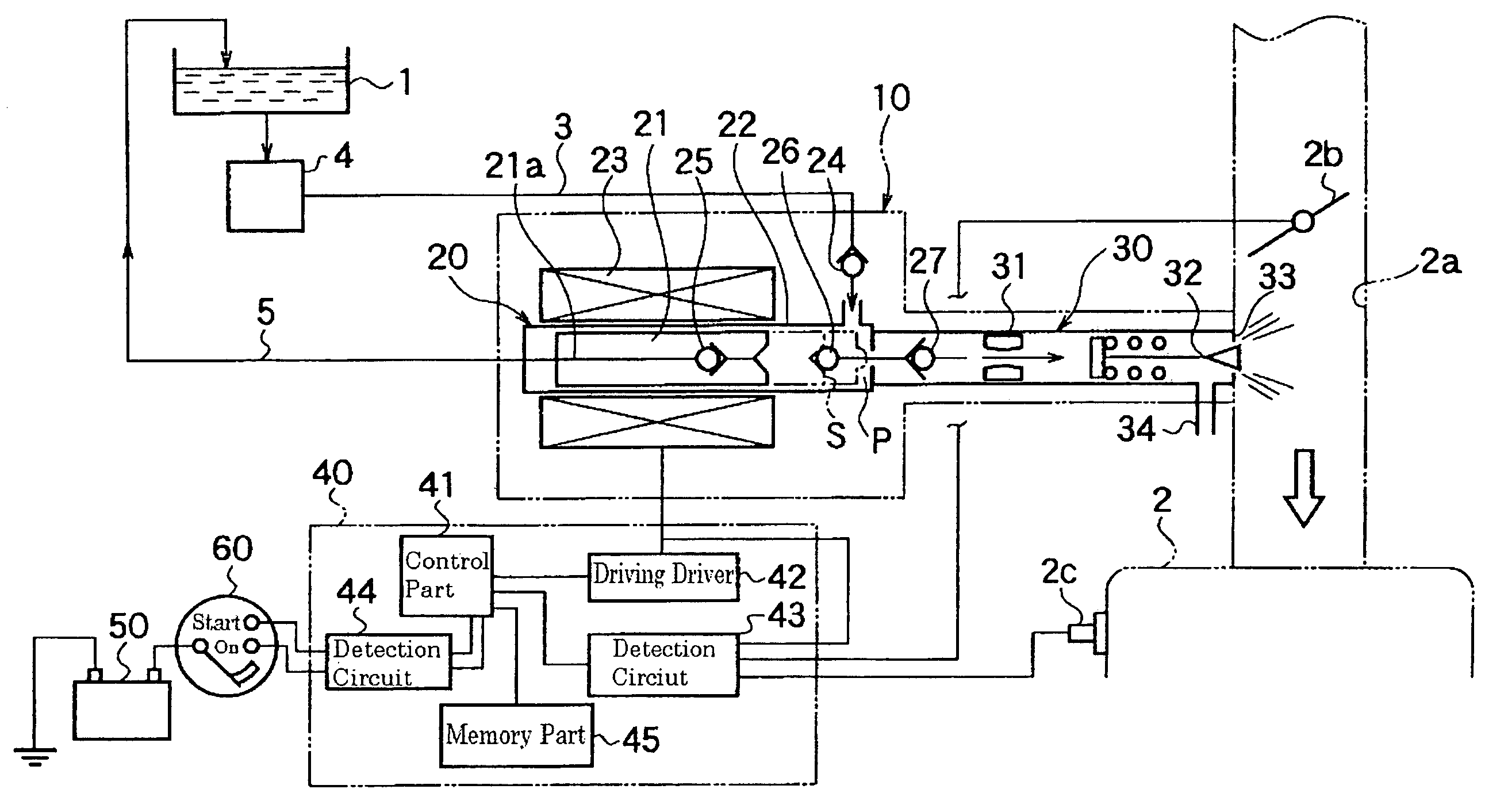
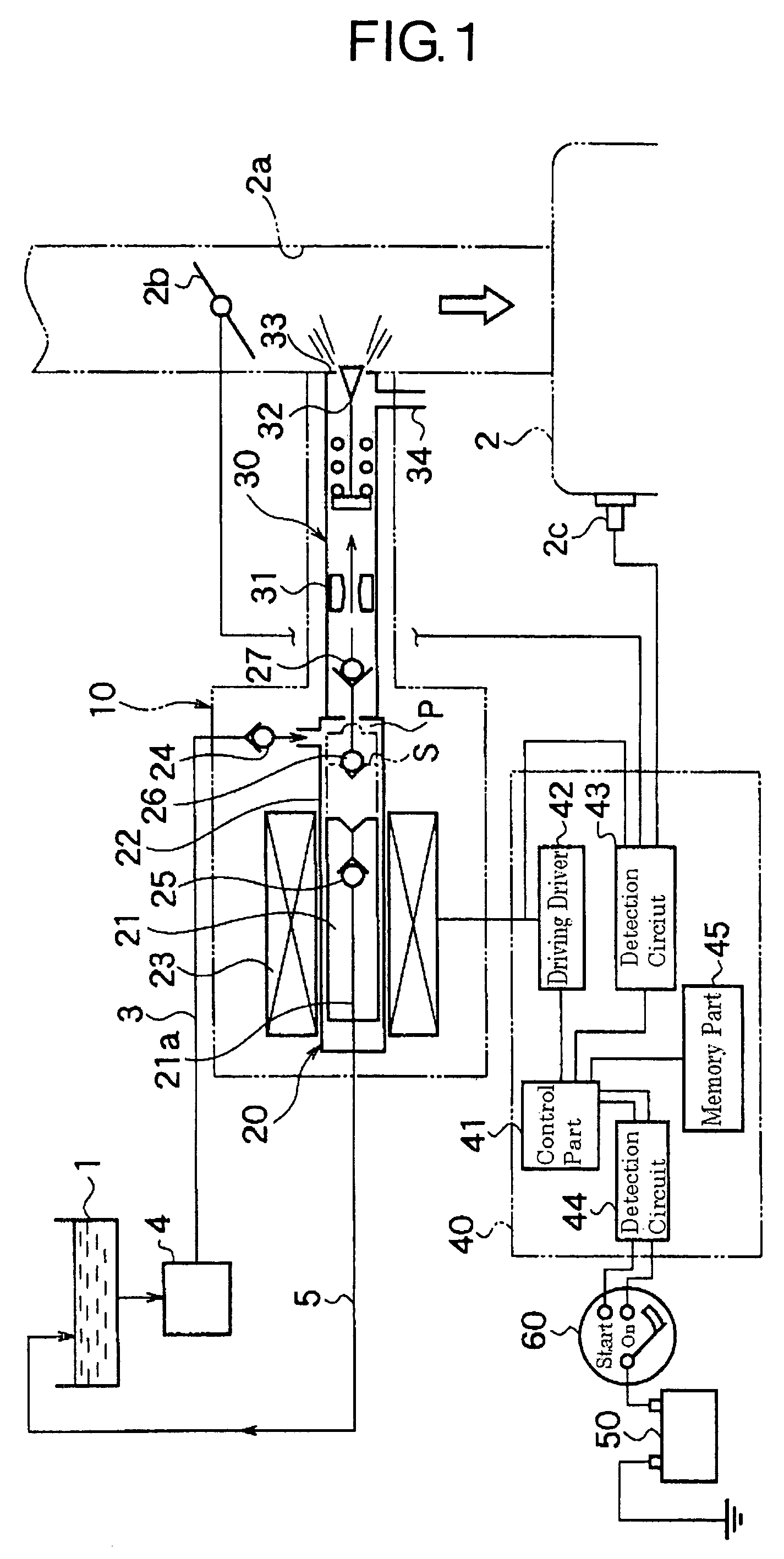
[0031]FIG. 1 is a schematic structural diagram which shows a fuel supply system of an engine mounted on a two-wheeled vehicle. As is shown in FIG. 1, this fuel supply system comprises a fuel tank 1 for the two-wheeled vehicle, a fuel injection device 10 which is disposed in the intake passage 2a of the engine 2, and which consists of an electromagnetically driven fuel injection pump 20 and an injection nozzle 30, a feed pipe 3 which supplies fuel, a low-pressure filter 4 which is disposed at an intermediate point in the feed pipe 3, a return pipe 5 which forms a return passage that returns a portion of the supplied fuel (excess fuel) to the fuel tank 1, an engine control unit (ECU) 40 used as control means for controlling the driving of the fuel injection pump 20, a battery 50 used as a power supply, a key switch 60 which performs on / off switching of the power supply for the sys...


PUM


Abstract

The present invention achieves an increase in the amount of vapor that is expelled, stabilized fuel injection and improved starting characteristics in a fuel injection pump. In an electromagnetically driven fuel injection pump 20 which allows fuel to escape into the return passage 5 in the initial region of the pressure-feeding stroke of the plunger 21, and which pressure-feeds fuel into the injection port 33 in the later region of the pressure-feeding stroke, pulse powering of the coil 23 that does not lead to the injection of fuel, i.e., pulse powering which is such that the plunger 21 performs a reciprocating motion through the initial region, is performed when the engine 2 is in an idle operating state, or in a state in which the engine 2 is re-started after being stopped immediately following high-load operation. As a result, vapor can be expelled with good efficiency, and the flow rate of the circulated fuel is increased so that the cooling effect is also increased, thus causing the generation of vapor to be suppressed as well, so that the starting characteristics or re-starting characteristics are improved.

Description

BACKGROUND OF THE INVENTION[0001]1. Field of the Invention[0002]The present invention relates to a method for driving a fuel injection pump which is used to supply fuel to an internal combustion engine (hereafter referred to simply as an “engine”), and more particularly relates to a method for driving a fuel injection pump used in engines that are mounted on two-wheeled vehicles or the like.[0003]2. Description of the Related Art[0004]For example, as is described in Japanese Patent Application Laid-Open No. 2001-221137, a fuel injection pump in which fuel conducted from a fuel tank by means of a feed pipe is pressure-fed by means of an electromagnetically driven plunger pump, fuel in the initial region of the pressure-feeding stroke is circulated back to the fuel tank by means of a return pipe, and fuel in the later region of the pressure-feeding stroke is injected into the intake passage from an injection nozzle, is known as a fuel injection pump used in engines mounted on two-whee...

Claims


Application Information

Patent Timeline
Patent Type & Authority Patents(United States)
IPC IPC(8): F02M37/04F02D41/06F02D41/08F02D41/30F02D41/40F02M37/08F02M37/20F02M51/04F02M57/02F02M61/08F02M69/04F02M69/08
CPCF02D41/065F02D41/3082F02M37/08F02M69/08F02M51/04F02M57/027F02M69/044F02M37/20F02D41/08F02D41/403F02M61/08F02M51/00
Inventor YAMAZAKI, SHIGERUHASHIMOTO, SHOGO
Owner MIKUNI CORP
Why Eureka
Try Eureka