Reduced noise aircraft stator vane

a technology of aircraft stator vane and reduced noise, which is applied in the direction of machines/engines, stators, liquid fuel engines, etc., to achieve the effect of effectively reducing the noise of the fan

Active Publication Date: 2006-09-05
IHI CORP
View PDF4 Cites 22 Cited by
  • Summary
  • Abstract
  • Description
  • Claims
  • Application Information

AI Technical Summary

Benefits of technology

[0009]According to the related art, a fan noise can be effectively reduced. However, further reduction of the fan noise is now intensively desired.
[0010]The present invention is achieved from the aforementioned view and an object thereof is provision of an aircraft engine, a fan thereof and a stator vane thereof having reduced noise generation.

Problems solved by technology

The wake flows and the stator vane surfaces interfere with each other so as to generate pressure fluctuation on the stator vane surfaces, which is a main source of a fan noise.

Method used


Image

  • Reduced noise aircraft stator vane
  • Reduced noise aircraft stator vane
  • Reduced noise aircraft stator vane

Examples


Embodiment Construction

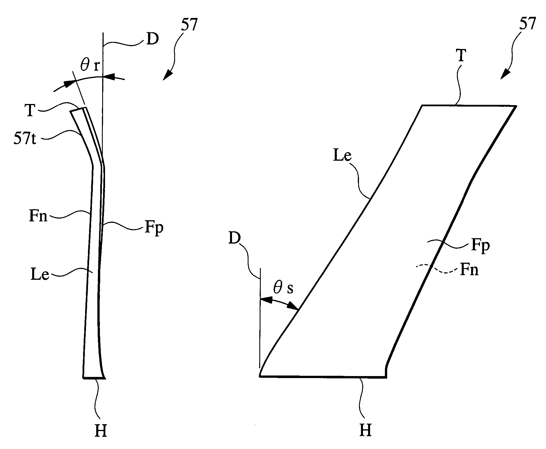
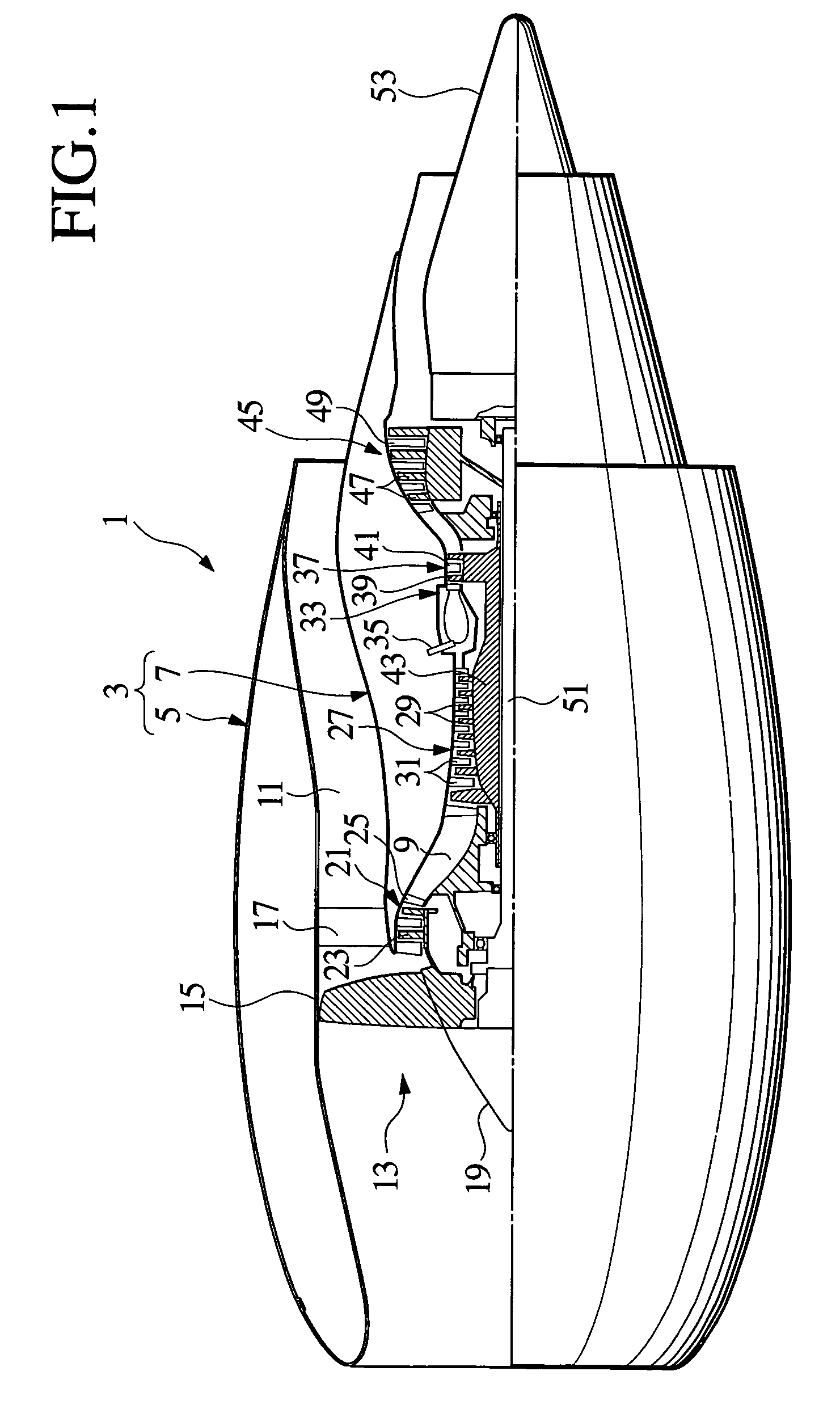
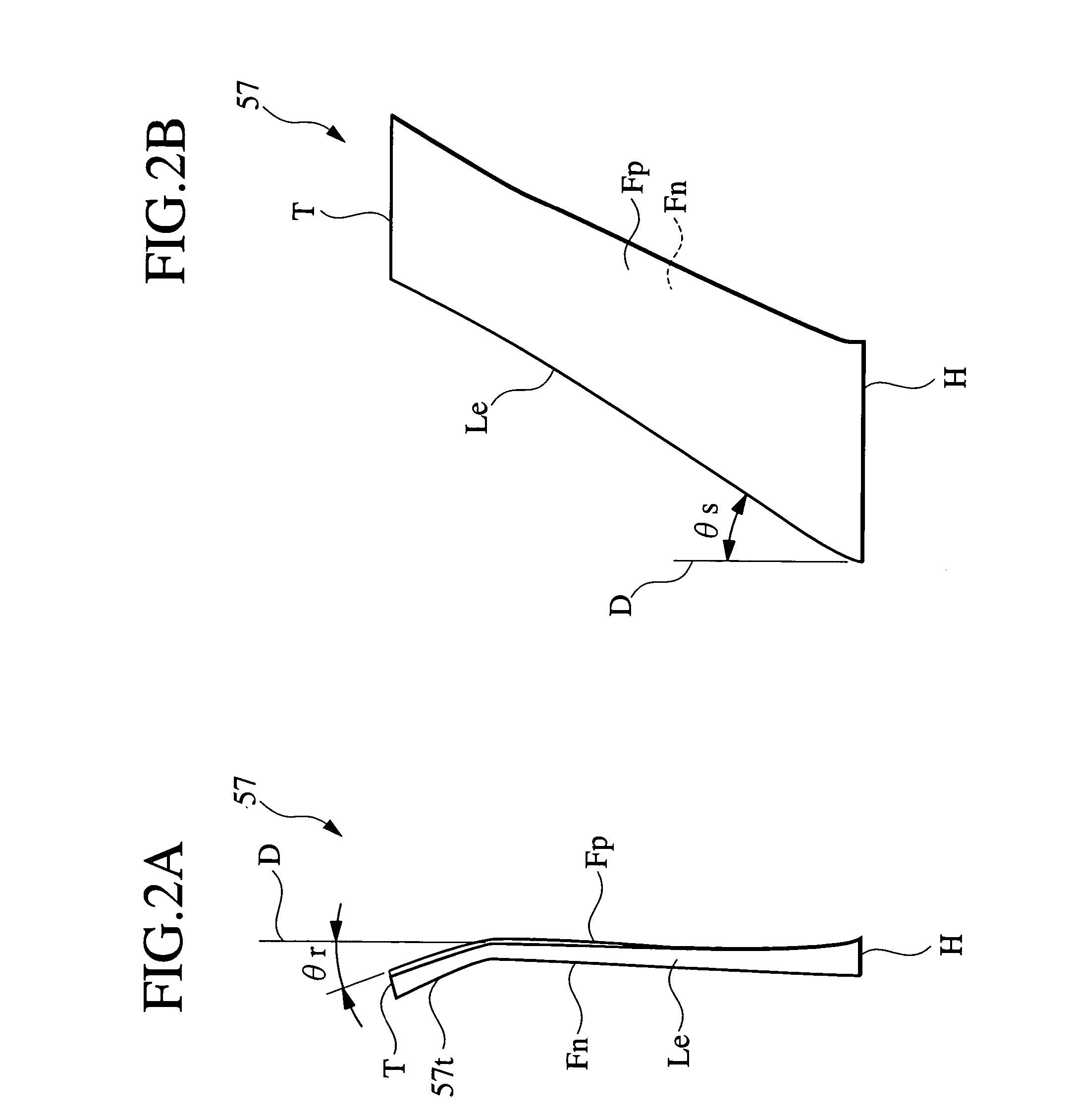
[0027]An embodiment of the present invention will be described hereinafter with reference to FIGS. 1 through 3B. Throughout the specification, definitions of directions such as fore and aft are consistent with directions of elements in practical use. For example, a fore end is illustrated on the left in FIGS. 1, 2B and 3A. In and out are defined by near and far from an axis of the engine. Further, some definitions such as leading, trailing, a pressure side and a suction side are defined by gas flow directions in its steady operation state and therefore some of them are dependent on rotation directions of elements disposed upstream. For ease of explanation, a fan rotor 15 is supposed to rotate in an anticlockwise direction from an anterior view. In this supposition, a spiral flow fed by the fan rotor 15 goes from the right to the left in FIG. 2A, therefore the suction side is illustrated on the left in FIG. 2A.

[0028]An aircraft engine 1 according to the embodiment of the present inve...


PUM


Abstract

A fan of an aircraft engine is provided with a rotating fan rotor for feeding air aftward as a spiral flow and a stator vane for rectifying the spiral flow to be an axial flow. The fan stator vane is provided with a hub end portion extending radially relative to a rotating axis of the fan rotor and a tip end portion leaning toward a suction side. Leading edges of the hub end portion and the tip end portion have sweepback angles of from 27 degrees to 33 degrees relative to a radial direction defined by the rotating axis.

Description

BACKGROUND OF THE INVENTION[0001]1. Field of the Invention[0002]The present invention relates to a gas turbine engine for an aircraft, a fan thereof and a fan stator thereof.[0003]2. Description of the Related Art[0004]An aircraft engine is generally provided with a fan for feeding air to circular main and bypass flow paths formed coaxially in a main body thereof.[0005]The fan is provided with a fan rotor rotatably disposed in the aircraft engine. The fan rotor is provided with plural rotor blades circumferentially arrayed. A fan stator is disposed adjacent to and aft of the fan rotor. The fan stator is provided with plural stator vanes circumferentially arrayed.[0006]When driving the fan rotor so as to rotate, the rotor blades feed air to the fan stator. Though the fed air flows into the fan stator as a spiral flow, the stator vanes is configured so as to rectify the air to be an axial flow fed into the bypass flow path.[0007]The air fed into the main flow path is utilized for comb...

Claims


Application Information

Patent Timeline
Patent Type & Authority Patents(United States)
IPC IPC(8): F01D5/12F01D5/14F04D29/54F04D29/66
CPCF01D5/141F04D29/542Y02T50/673Y02T50/671F04D29/544Y02T50/60
Inventor TSUCHIYA, NAOKIKATO, DAI
Owner IHI CORP
Why Eureka
Try Eureka