

Distribution line structure for electric power supply
a technology of distribution line and electric power supply, which is applied in the direction of insulated conductors, flat/ribbon cables, cables, etc., can solve the problems of considerable leakage of electromagnetic field, and achieve the effect of excellent productivity
- Summary
- Abstract
- Description
- Claims
- Application Information
AI Technical Summary
Benefits of technology
Problems solved by technology
Method used
Image

Examples
first embodiment
[0049]the present invention will be described hereinafter with reference to FIGS. 1–21.
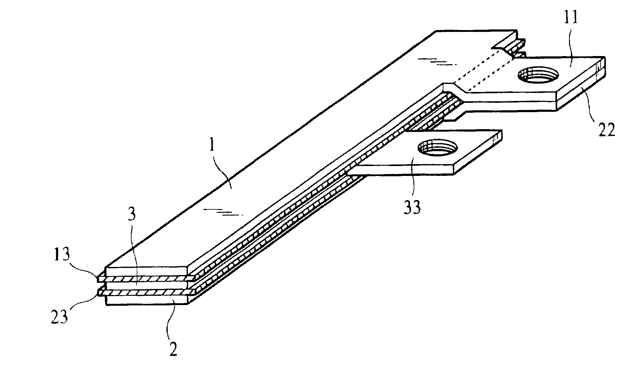
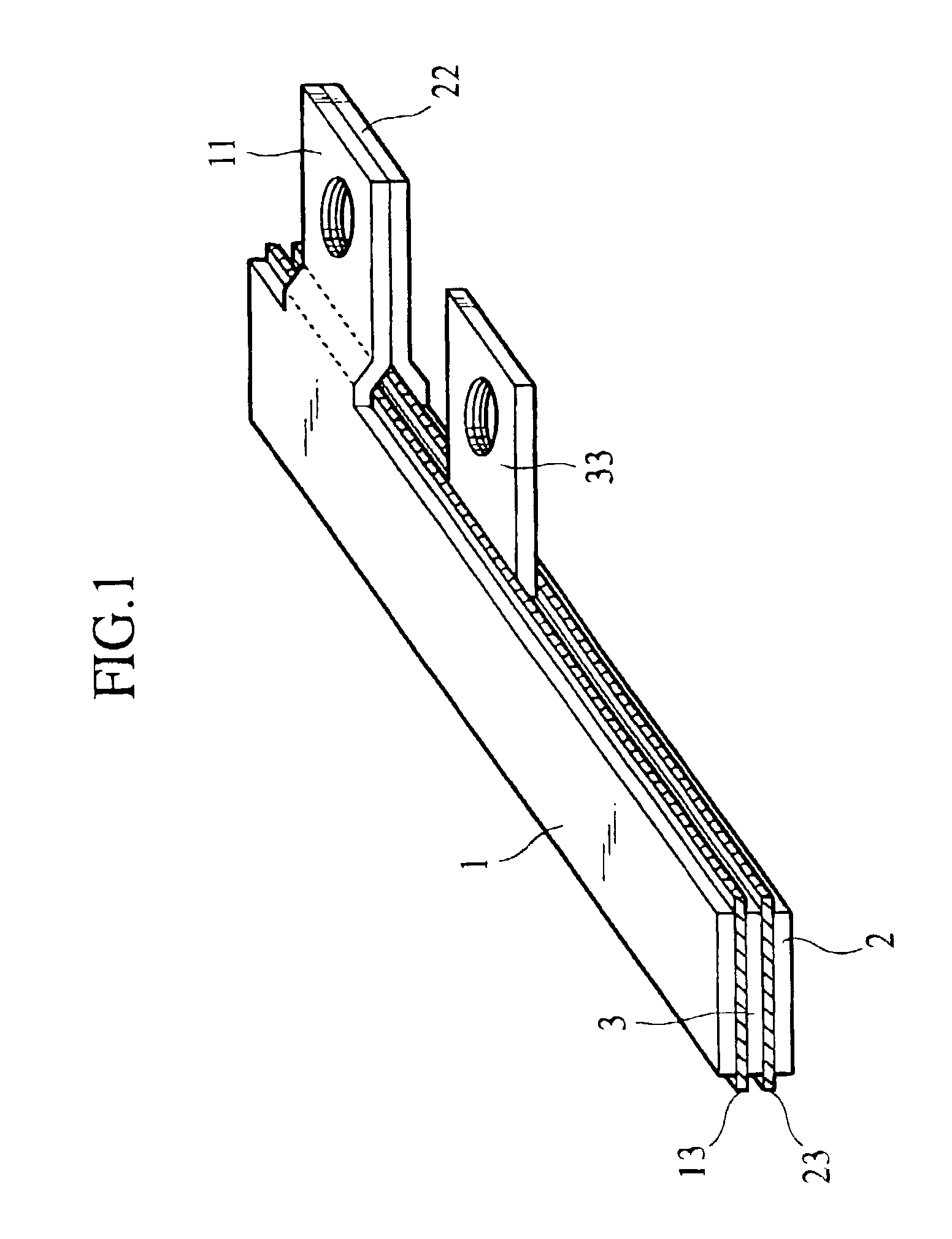
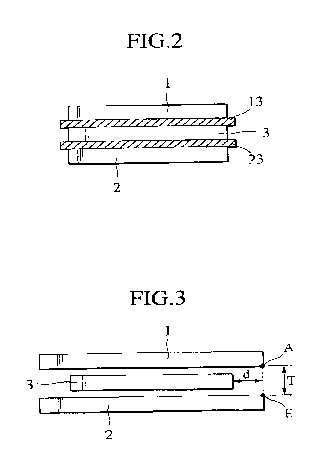
[0050]The distribution line structure is provided with a pair of first conductors 1 and 2 and a second conductor 3. The first conductors 1 and 2 conduct an electric current and the second conductor 3 conducts a counter electric current thereof. The first and second conductors 1, 2 and 3 are made of conductive material such as copper and are formed in flat strips and layered, as shown in FIGS. 1–3.
[0051]The distribution line structure is further provided with insulator layers 13 and 23. The insulator layer 13 is put between the first conductor 1 and the second conductor 2 and the insulator layer 23 is put between the second conductor 2 and the first conductor 3. The insulator layers 13 and 23 are made of insulative material such as mica based insulator or insulative resin. The insulator layers 13 and 23 are formed certainly wider than the conductors 1, 2 and 3 so as to prevent a discharge between p...
fourth embodiment
[0067]FIG. 9 shows a cross section of the structure of the connection portions 11, 22 and 33. The first conductors 1 and 2 are respectively provided with first connection portions 11 and 22 and the connection portion 11 is projected downward to be in contact with the connection portion 22 through a through hole of the second conductor 3 so as not to touch with the second conductor 3. The first connection portions 11 and 22 are provided with a screw hole to which a screw S1 is inserted so as to connect with an auxiliary apparatus. The first conductors 1 and 2 are provided with through holes so that a vicinity of a screw hole of the connection portion 33 is exposed. A screw S2 is inserted into the screw hole of the connection portion 33 so as to connect with the auxiliary apparatus. As the auxiliary apparatus, a power semiconductor module or a capacitor for a ripple filter is exemplified. An edge structure described later may be applied to the edges of the throughholes so as to suppre...
second embodiment
[0076]the present invention will be described hereinafter with reference to FIGS. 22–24.
[0077]The distribution line structure is provided with a pair of first conductors 1 and 2, second conductors 3 and 5 and a third conductor 4. All the conductors 1–5 are made of conductive material such as copper and are formed in flat strips. The second and third conductors 3–5 are sandwiched between the first conductors 1 and 2. The third conductor 4 is positioned in a center and the second conductors 3 and 5 are aligned on both sides thereof. An insulator layer 12 is put between the first, second and third conductors 1–5. Though FIG. 22, shows the insulator layer 12 as being integrally formed, the insulator layer 12 may be separated into several insulator sheets.
[0078]A current may be conducted on any pair of conductors selected from the first, second and third conductors. For example, when the third conductor 4 conducts a current, the first conductors 1 and 2 may conduct a counter current. In ...
PUM
| Property | Measurement | Unit |
|---|---|---|
| Length | aaaaa | aaaaa |
| Shape | aaaaa | aaaaa |
| Electrical conductor | aaaaa | aaaaa |
Abstract
Description
Claims
Application Information