Method for calibrating smart antenna array systems in real time

a real-time calibration and antenna array technology, applied in the field of wireless communication system smart antenna technology, can solve the problems of unfavorable real-time calibration, and achieve the effects of reducing transmitting power, improving beams of smart antenna array, and good implementation of smart antenna technology

Inactive Publication Date: 2006-09-05
DATANG MOBILE COMM EQUIP CO LTD
View PDF7 Cites 17 Cited by
  • Summary
  • Abstract
  • Description
  • Claims
  • Application Information

AI Technical Summary

Benefits of technology

[0024]The method of the present invention has many advantages including one of short computation time and simple controls. It is especially suitable for a smart antenna array in the third generation mobile communication system with high chip rate, though it may be used in other applications.
[0026]By calibrating a smart antenna array with the method of the present invention, beams of the smart antenna array are greatly improved and the transmitting powers are decreased, resulting in a good implementation of the smart antenna technology.

Problems solved by technology

In addition, the transmitting calibration as described above is carried out with one link in the transmitting state at a time while all other links are in the receiving state, which is unfavorable for fast real-time calibration.

Method used


Image

  • Method for calibrating smart antenna array systems in real time
  • Method for calibrating smart antenna array systems in real time
  • Method for calibrating smart antenna array systems in real time

Examples


Embodiment Construction

[0031]The present invention now will be described more fully with reference to the accompanying drawings, in which some, but not all embodiments of the invention are shown. Indeed, this invention may be embodied in many different forms and should not be construed as limited to the embodiments set forth herein. Rather, these embodiments are provided so that this disclosure will satisfy applicable legal requirements. Like numbers refer to like elements throughout.

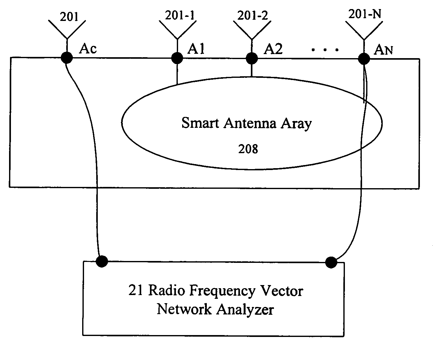
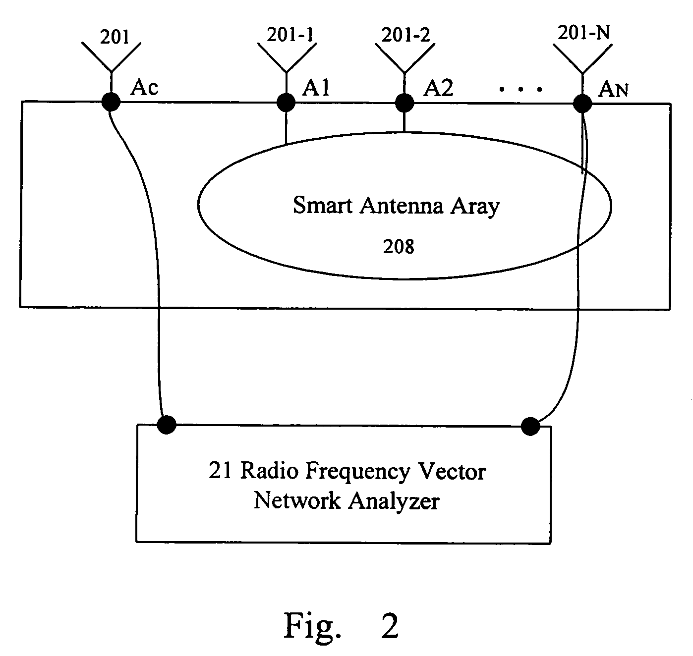
[0032]The method of the present invention is proposed on the basis of an antenna array which is a passive microwave (radio frequency) network. Characteristics of mutual coupling between each antenna element of this antenna array and the calibration antenna element remain unchanged at a given working frequency provided that the design of the antenna array product has been finalized and the structure thereof is fixed. Therefore, before delivery of the antenna array, each antenna element of the antenna array can be tested relati...


PUM


Abstract

Transmitting and receiving compensation coefficients of each antenna element relative to a calibration antenna element are obtained in the pre-calibration of a smart antenna. After the antenna array is installed, in transmitting calibration, amplitude and phase response of each transmitting link is computed according to the calibration signals received by the calibration link and, together with the transmitting compensation coefficient obtained in the pre-calibration, the compensation coefficient of each transmitting link is computed to compensate the downlink data of a base station. In receiving calibration, the amplitude and phase response of each receiving link is computed based on the signals received by the receiving links and, together with the receiving compensation coefficient obtained in pre-calibration, the compensation coefficient of each receiving link is computed to compensate the uplink data of the base station. The calibration signal of each antenna element is generated by a periodic cycling shift of a basic calibration sequence.

Description

CROSS-REFERENCE TO RELATED APPLICATIONS[0001]This application is a continuation of PCT / CN2003 / 001118 filed Dec. 25, 2003, which was published under the Patent Cooperation Treaty in Chinese on Jul. 15, 2004, and which is hereby incorporated herein in its entirety by reference, and this application also claims the benefit of Chinese Patent Application No. 02158623.3, filed Dec. 25, 2002.FIELD OF THE TECHNOLOGY[0002]The present invention generally relates to smart antenna technology of wireless communication systems, more specifically, to a method for calibrating a smart antenna array system in real time.BACKGROUND OF THE INVENTION[0003]In modern wireless communication systems, especially in a Code Division Multiple Access (CDMA) wireless communication systems, smart antennas have been one of the most attractive technologies. By means of smart antenna arrays and the technology based on digital signal processing, wireless base stations can achieve self-adaptive beam forming of both tran...

Claims


Application Information

Patent Timeline
Patent Type & Authority Patents(United States)
IPC IPC(8): H04B7/005H04B17/00H01Q3/26
CPCH01Q3/267H04W16/28H04B7/02
Inventor TAN, ZHELI, FENG
Owner DATANG MOBILE COMM EQUIP CO LTD
Why Eureka
Try Eureka