Color-filter substrate assembly, method for manufacturing the color-filter substrate assembly, electro-optical device, method for manufacturing the electro-optical device, and electronic apparatus

a technology of color filter substrate and assembly, which is applied in the direction of non-linear optics, instruments, optics, etc., can solve the problems of cost increase, reduced light reflectance, and complicated manufacturing process, and achieve excellent functionality

Inactive Publication Date: 2006-09-05
138 EAST LCD ADVANCEMENTS LTD
View PDF13 Cites 1 Cited by
  • Summary
  • Abstract
  • Description
  • Claims
  • Application Information

AI Technical Summary

Benefits of technology

[0012]In view of the above problem, the present invention has been developed. It is an object of the present invention to provide a color-filter substrate assembly which is inexpensive, and provides, in the simple structure thereof, excellent functionality with the light-shield function, such as of a black mask, and the scattering function for a reflective-type display when the color-filter substrate assembly is used in a liquid-crystal display device (especially a reflective-type liquid-crystal display device or a transflective-type liquid-crystal display device), and also to provide a method for manufacturing the color-filter substrate assembly, a liquid-crystal display device, a method for manufacturing the liquid-crystal display device, and electronic apparatus.
[0015]When the color-filter substrate assembly thus constructed is used in an electro-optical device (such as a reflective-type liquid-crystal display device or a transflective-type liquid-crystal display device), the color-filter substrate assembly becomes inexpensive and provides, in the simple structure thereof, excellent functionality with a light-shield function, such as of a black mask, and a scattering function for a reflective-type display.
[0018]In the above arrangements, the color-filter substrate assembly is efficiently manufactured at low costs.
[0021]In the above arrangements, a low-cost electro-optical device with excellent functionality results.
[0024]In the above arrangements, an electro-optical device with excellent functionality is manufactured at low costs.
[0026]In the above arrangements, low-cost electronic apparatus with excellent functionality is provided.

Problems solved by technology

In the conventional liquid-crystal display device, both the light-shield layer 700 and the light-shield layer (black mask or black matrix) 525 must be formed, thereby not only complicating the manufacturing process and resulting in a cost increase, but also giving rise to a functional problem of a drop in light reflectance due to unwanted light-shield layer (residuals) on the reflective layer.

Method used


Image

  • Color-filter substrate assembly, method for manufacturing the color-filter substrate assembly, electro-optical device, method for manufacturing the electro-optical device, and electronic apparatus
  • Color-filter substrate assembly, method for manufacturing the color-filter substrate assembly, electro-optical device, method for manufacturing the electro-optical device, and electronic apparatus
  • Color-filter substrate assembly, method for manufacturing the color-filter substrate assembly, electro-optical device, method for manufacturing the electro-optical device, and electronic apparatus

Examples


first embodiment

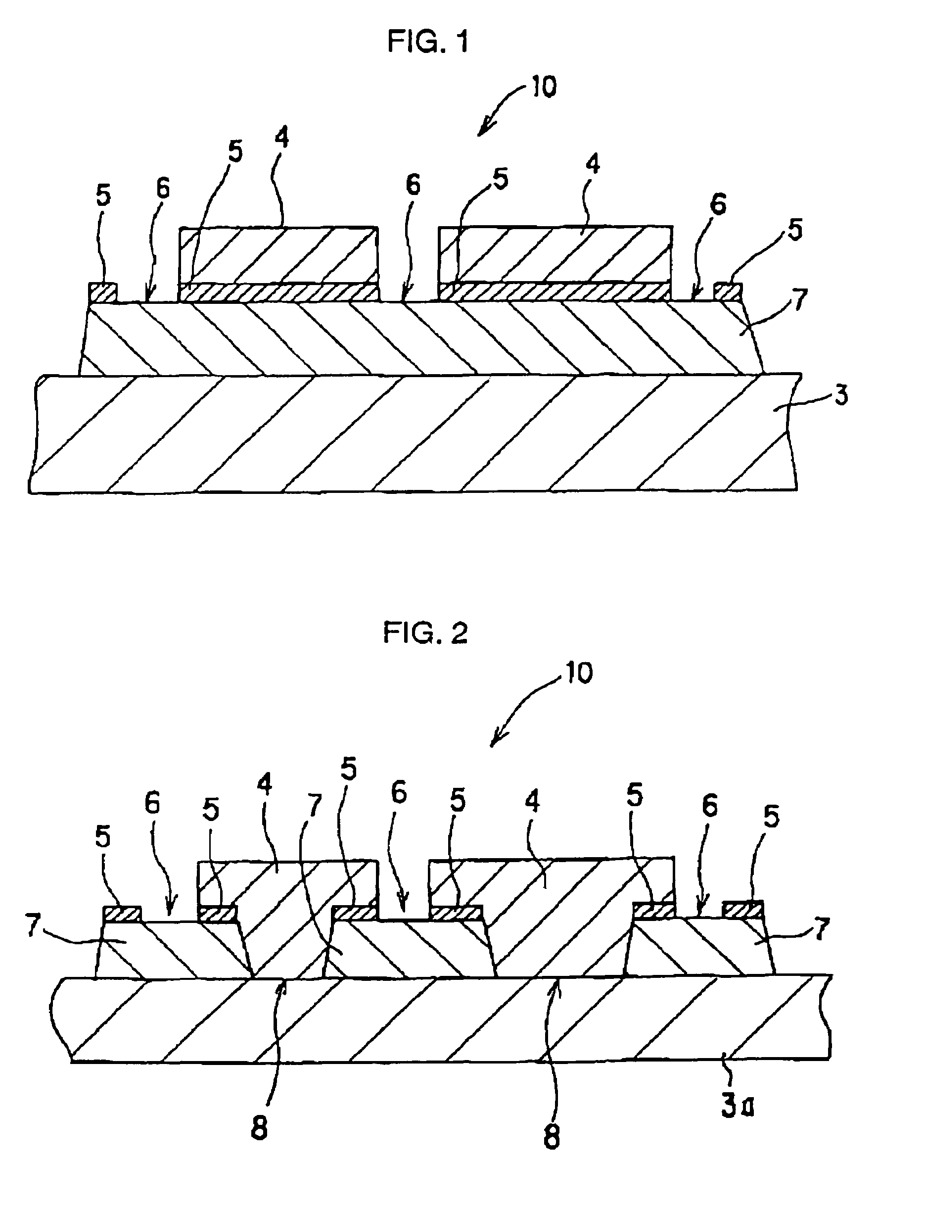
[0042]Referring to FIG. 1, a color-filter substrate assembly 10 in a first embodiment includes a substrate 3, a light-shield layer 7 which is arranged on the substrate 3 and substantially shields light, a reflective layer 5 which is arranged on the light-shield layer 7 and substantially reflects light, and a color layer 4 arranged on the reflective layer 5. The reflective layer 5 has an aperture 6 and is covered with the color layer 4.

[0043]Referring to FIG. 1, spacing is allowed between adjacent color layers 4. Alternatively, adjacent color layers 4 may be contiguous to each other. In the perspective view thereof from above, the aperture 6 surrounds each pixel region. The same is true of the following embodiments.

[0044]Since the reflective layer 5 has the aperture 6 in this way, the light-shield layer 7 is exposed so that the contrast of the light-shield layer 7 is improved.

[0045]In this arrangement, light from the outside is reflected from the reflective layer 5, and the reflected...

second embodiment

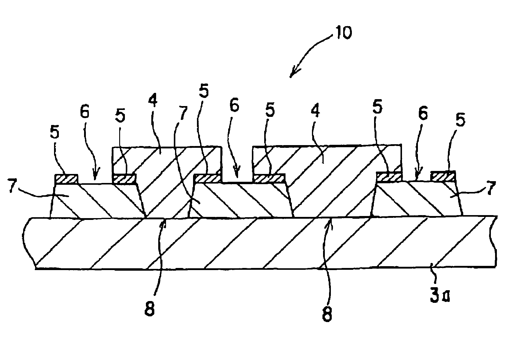
[0052]Referring to FIG. 2, the color-filter substrate assembly 10 in a second embodiment includes a substrate 3a which is substantially transparent, a light-shield layer 7 arranged on the substrate 3a, a reflective layer 5 arranged on the light-shield layer 7, and a color layer 4 arranged on the substrate 3a. The light-shield layer 7 has apertures 8, and the reflective layer 5 has apertures 6 and is covered with the color layer 4.

[0053]Since the light-shield layer 7 has the apertures 8, incident light from the backlight passes through the aperture 8, and transmits through the color layer 4. The transmitted light thus presents an image (in the transmissive-type display). With the reflective-type display with the reflective layer 5, the color-filter substrate assembly appropriately finds application in a low-cost transflective-type display device having excellent functionality. This embodiment employs a substantially transparent substrate 3a, and the rest of the construction remains u...

third embodiment

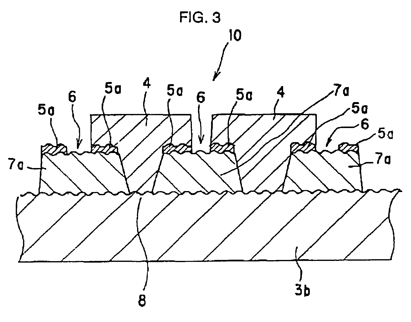
[0054]Referring to FIG. 3, the color-filter substrate assembly 10 in a third embodiment employs a substrate 3b having a rugged surface instead of the substrate 3a in the second embodiment. Furthermore, instead of the light-shield layer 7 and the reflective layer 5, a light-shield layer 7a and a reflective layer 5a, each having a rugged surface, are used. Specifically, the color-filter substrate assembly 10 of the third embodiment includes the substrate 3b which is substantially transparent and has a rugged surface, the light-shield layer 7a arranged on the substrate 3b, and having the rugged surface conformal to the rugged surface of the substrate 3b, the reflective layer 5a arranged on the light-shield layer 7a and having the rugged surface conformal to the rugged surface of the light-shield layer 7a, and a color layer 4 arranged on the substrate 3b. The light-shield layer 7a has apertures 8, and the reflective layer 5a has apertures 6 and is covered with the color layer 4.

[0055]In...


PUM


Abstract

A color-filter substrate assembly 10 includes a substrate 3b having a rugged surface, a light-shield layer 7a arranged on the substrate 3b, and having a rugged surface conformal to the rugged surface of the substrate 3b, a reflective layer 5 arranged on the light-shield layer 7a and having a rugged surface conformal to the rugged surface of the light-shield layer 7a, and a color layer 4 arranged on the substrate 3b. The light-shield layer 7a has an aperture 8, and the reflective layer 5a has an aperture 6, and is covered with the color layer 4. The invention provides a color-filter substrate assembly which is inexpensive, and provides, in the simple structure thereof, excellent functionality with a light-shield function, such as of a black mask, and a scattering function for a reflective-type display when the color-filter substrate assembly is used in an electro-optical device (such as a reflective-type liquid-crystal display device or a transflective-type liquid-crystal display device).

Description

CROSS-REFERENCE TO RELATED APPLICATION[0001]This application is a continuation of U.S. Ser. No. 10 / 214,393 filed on Aug. 6, 2002, now abandoned claiming priority to Japanese Application Nos. 2001-239608 filed Aug. 7, 2001 and 2002-195213 filed Jul. 3, 2002, all of which are hereby incorporated by reference.BACKGROUND OF THE INVENTION[0002]1. Technical Field[0003]The present invention relates to a color-filter substrate assembly, a method for manufacturing the color-filter substrate assembly, an electro-optical device, a method for manufacturing the electro-optical device, and electronic apparatus. More specifically, the present invention relates to a color-filter substrate assembly which is inexpensive, and provides excellent functionality with a light-shield function, such as a black mask, and a scattering function for a reflective-type display when the color-filter substrate assembly is used in a liquid-crystal display device (such as a reflective-type liquid-crystal display devic...

Claims


Application Information

Patent Timeline
IPC IPC(8): G02F1/1335G02F1/136
CPCG02F1/133555G02F1/133512G02F1/133514
Inventor NAKANO, TOMOYUKITAKIZAWA, KEIJITANAKA, CHIHIROKANEKO, HIDEKI
Owner 138 EAST LCD ADVANCEMENTS LTD
Why Eureka
Try Eureka