Balancing a rotatable body in multiple planes using invertible balancing plugs

a technology of balancing plugs and rotatable bodies, applied in the direction of casings/cabinets/drawers, casings/cabinets/drawers, instruments, etc., can solve the problem of adversely affecting the ability to accurately position the read/write head(s) of the disk driv

Inactive Publication Date: 2006-09-05
MAXTOR
View PDF9 Cites 9 Cited by
  • Summary
  • Abstract
  • Description
  • Claims
  • Application Information

AI Technical Summary

Benefits of technology

[0024]In one embodiment of the second aspect, all balancing plugs are selected from a kit or collection of balancing plugs that are specific to the rotatable body. This kit may include a plurality of balancing plug configurations, and each balancing plug configuration may be available in one or more weights (e.g., by changing the density of all or part of the balancing plug configuration). For instance, the weight of a given balancing plug configuration may be established by the density of its body, by the number of balancing weight receptacles included on its body, by the density of the balancing weight(s) disposed within a particular receptacle on its body, or any combination thereof. Preferably, each balancing plug within the noted kit is of the same length, and with the center of gravity of each balancing plug being located the same distance from one of its ends. This then allows a balancing plug within the noted kit to be used to balance the rotatable body in two different planes, simply by inverting the position of the balancing plug within the rotatable body.
[0025]The nature of the balancing plugs used in relation to the second aspect provides a number of advantages. One is that all balancing plugs may be installed from a common side of the rotatable body, and yet still provide balancing in two vertically spaced planes (e.g., dual plane balancing). Since all balancing plugs may be installed from a common side of the rotatable body and for the case where the same is in the form of a disk drive motor / disk assembly, this also allows the balancing to be undertaken at a time when the motor / disk assembly is installed within the disk drive. In one embodiment, the balancing in accordance with the second aspect is done at a time when the motor / disk assembly is rotatably mounted on a base plate of the disk drive. However, balancing of the motor / disk assembly in accordance with the second aspect could be undertaken prior to installing the same in the disk drive.
[0026]Each balancing plug used in relation to the second aspect may include at least one flexible flange. Any such flexible flange may be used to retain the balancing plug in a desired vertical position within its corresponding balancing plug hole in the rotatable body by a frictional engagement. The outer diameter of each such flexible flange may be such that it is flexed inwardly when directing the corresponding balancing plug within its corresponding balancing plug hole in the motor / disk assembly and into the desired vertical position. The resulting “outwardly directed” flexing of each flange on each balancing plug establishes a sufficient frictional engagement with a wall defining its corresponding balancing plug hole to retain the balancing plug in a desired vertical position in the rotatable body. Although one or more flexible flanges at a single location along the length of the balancing plug may generate sufficient forces to retain the balancing plug in a desired vertical position within its corresponding balancing plug hole, having one or more of these flanges at multiple locations along the length of the balancing plug may facilitate the use of the same in either of two positions in at least some cases where the rotatable body is in the form of a motor / disk assembly (e.g., to balance in either of two different planes simply by inverting the balancing plug). Other ways of maintaining each balancing plug in a desired vertical position within its corresponding balancing plug hole may be appropriate.

Problems solved by technology

Even a slight imbalance of the rotating motor / disk assembly may then generate rather significant forces that can adversely affect the ability to accurately position the read / write head(s) of the disk drive at the correct track of its corresponding data storage disk.

Method used


Image

  • Balancing a rotatable body in multiple planes using invertible balancing plugs
  • Balancing a rotatable body in multiple planes using invertible balancing plugs
  • Balancing a rotatable body in multiple planes using invertible balancing plugs

Examples


Embodiment Construction

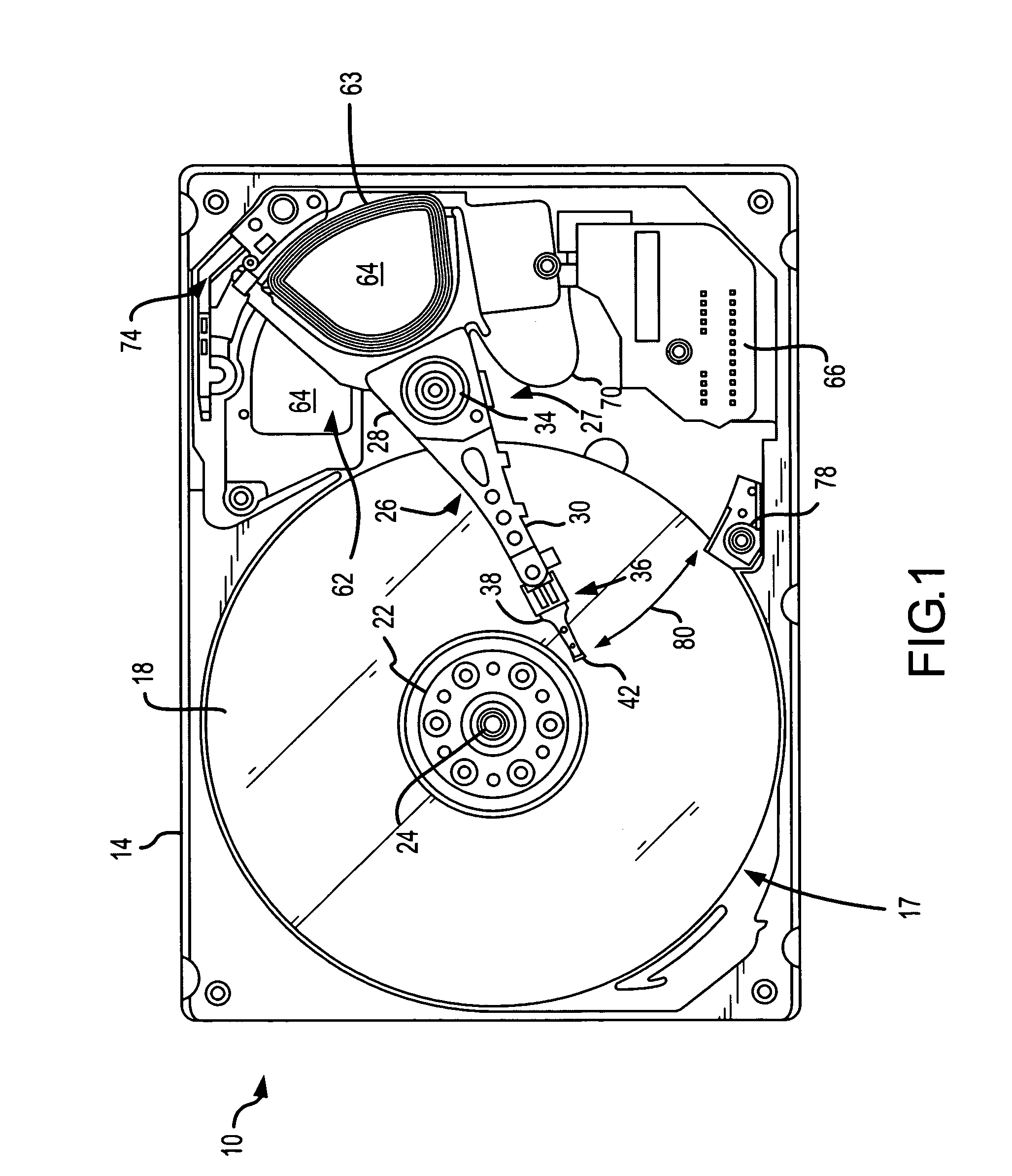
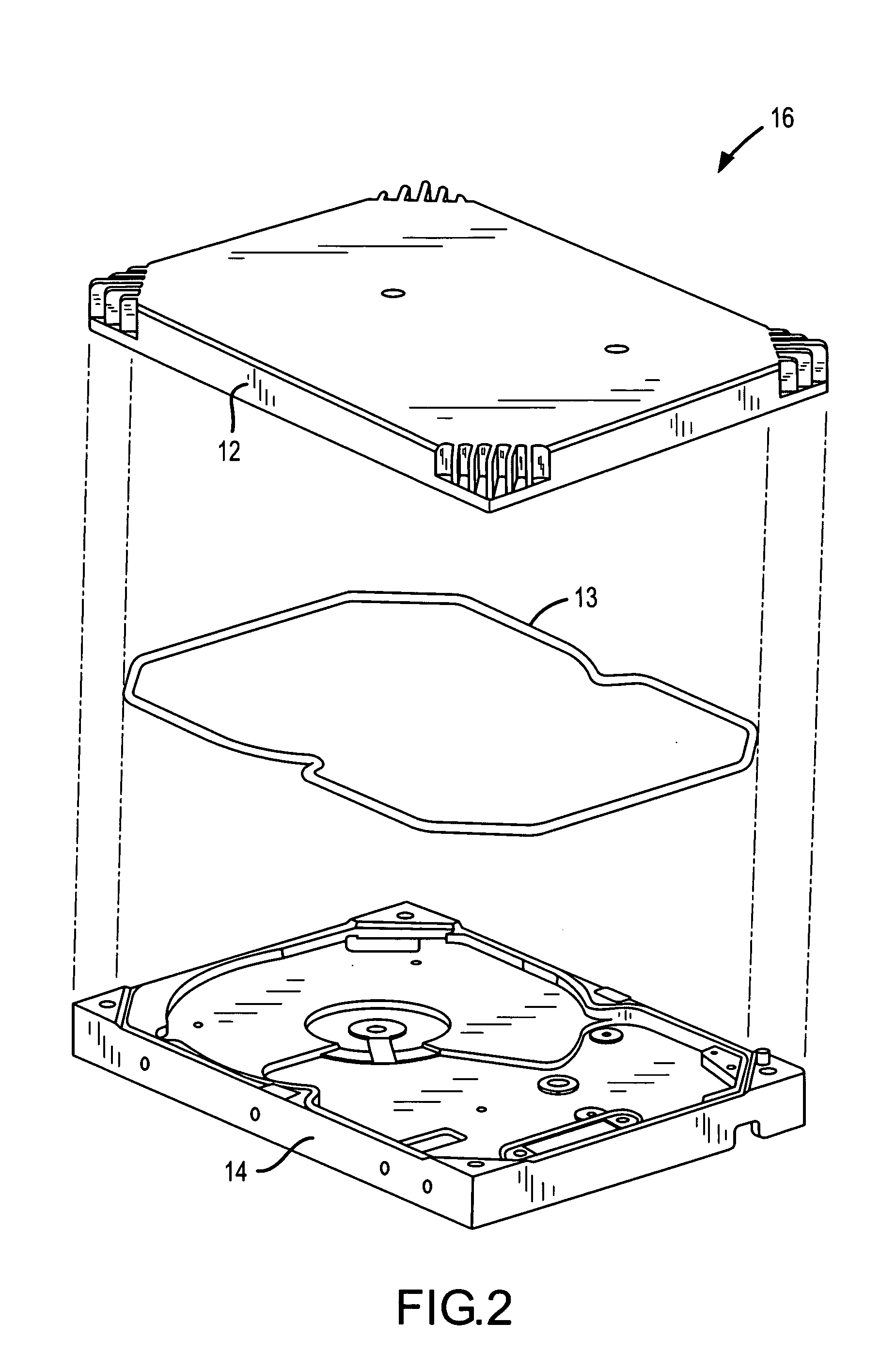
[0048]The present invention will now be described in relation to the accompanying drawings that at least assist in illustrating its various pertinent features. One embodiment of a disk drive 10 is illustrated in FIGS. 1–4. The disk drive 10 generally includes a disk drive housing 16 of any appropriate configuration that defines an enclosed space for the various disk drive components. Here the housing 16 includes a base plate 14 that is typically detachably interconnected with a cover 12. A suitable gasket 13 may be disposed between the cover 12 and the base plate 14 to enhance the seal therebetween.

[0049]The disk drive 10 includes one or more data storage disks 18 of any appropriate computer-readable data storage media. Typically both of the major surfaces of each data storage disk 18 include a plurality of concentrically disposed tracks for data storage purposes. Each disk 18 is mounted on a hub by a disk clamp 22, and the hub is rotatably interconnected with the disk drive base pl...


PUM

PropertyMeasurementUnit
distanceaaaaaaaaaa
distanceaaaaaaaaaa
distanceaaaaaaaaaa

Abstract

Multiple balancing plugs (114) preferably have a common length and a common offset center of gravity (130) in the length dimension for providing dual plane balancing of a rotatable body (100). The rotatable body (100) includes a plurality of balancing plug holes (112a–f) for receipt of a balancing plug (114) as desired/required to address an imbalance associated with the rotatable body (100). One or more balancing plugs (114) may be disposed within the rotatable body (100) in a first orientation such that their respective centers of gravity (130) are disposed within a first plane (134). One or more balancing plugs (114) may be disposed within the rotatable body (100) in a second, opposite orientation such that their respective centers of gravity (130) are disposed within a second plane (138) that is spaced from the first plane (134).

Description

CROSS-REFERENCE TO RELATED APPLICATIONS[0001]This patent application claims priority under 35 U.S.C. §119(e) to U.S. Patent Application Ser. No. 60 / 452,618, that is entitled “Reversible Plug Capable of Dual Plane Balance,” that was filed on Mar. 6, 2003, and the entire disclosure of which is incorporated by reference in its entirety herein.FIELD OF THE INVENTION[0002]The present invention generally relates to rotating bodies and, more particularly, to balancing a rotatable body in at least two vertically spaced reference planes using balancing plugs with a known offset of their respective center of gravity that allows any such balancing plug to be used for balancing in either of two different, vertically spaced planes simply by inverting the position of the balancing plug in the rotatable body.BACKGROUND OF THE INVENTION[0003]Spindle motors are a commonly used in disk drives to simultaneously rotate each data storage disk being used by the disk drive. A stationary spindle or motor s...

Claims


Application Information

Patent Timeline
Patent Type & Authority Patents(United States)
IPC IPC(8): G11B17/00
CPCG11B17/038Y10T74/2109
Inventor BUZEK, MARK A.JOHNSON, GALE D.WHITT, III, DAVID O.
Owner MAXTOR
Why Eureka
Try Eureka