Feed roll construction

a technology of feed rolls and construction, applied in the direction of conveyor parts, rollers, mechanical conveyors, etc., can solve the problems of large product loss, substantial number of kernels rendered unusable, and rupturing of some kernels, and achieve the effect of adequate frictional engagement and enhanced adhesion

Inactive Publication Date: 2006-06-22
ANDERSON RONALD L
View PDF5 Cites 3 Cited by
  • Summary
  • Abstract
  • Description
  • Claims
  • Application Information

AI Technical Summary

Benefits of technology

[0005] Present roll construction utilizes a molded, resilient body which advances articles in succession along a path with minimal impact and damage to the article including food products. Inclined roll surfaces yield upon contact with the article. The inclined, product engaging surfaces, momentarily yield providing adequate frictional engagement with the ear to advance same. Roll walls avoid presenting sharply defined, firm edges to the kernels. Upon ear passage the roll returns to a normal configuration. The use of a resilient synthetic material, such as urethane, enhances adhesion between the feed roll and the article being propelled to the extent, at least in some uses, dispensing with a metal prong heretofore used on a feed roll to assure driving contact with the article.

Problems solved by technology

The lugs on existing rolls have angular surfaces resulting in line contact with and the rupturing of some kernels which become waste as damaged kernels are often not utilized in the end product.
To the extent known, feed rolls of corn cutting machines have lug bearing surfaces and, even though the roll material is somewhat resilient, a substantial number of kernels are rendered unusable.
What may initially appear as a minimal loss constitutes a sizeable loss of product when the high volume of processed corn is considered even over a short period of time.

Method used


Image

  • Feed roll construction
  • Feed roll construction
  • Feed roll construction

Examples


Embodiment Construction

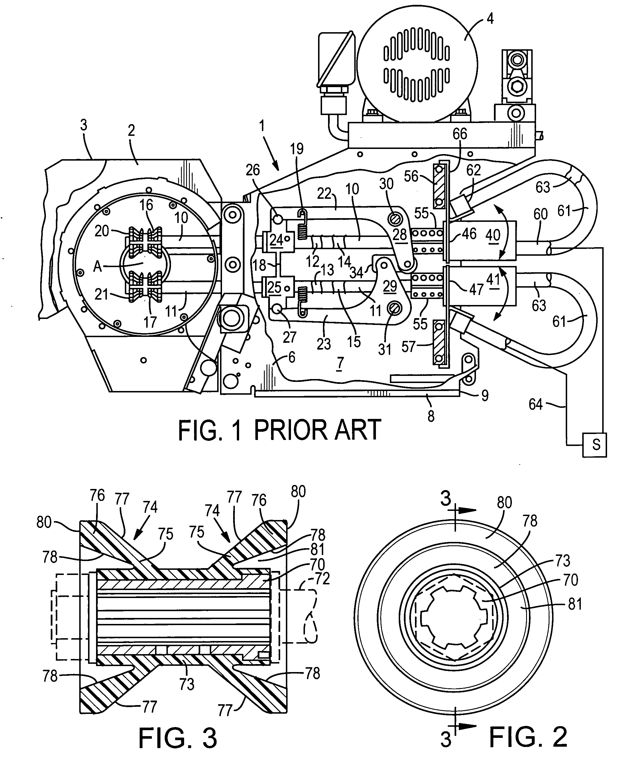
[0012] With continuing attention to the drawings wherein applied reference numerals indicate parts similarly hereinafter identified, the reference numeral 1, in U.S. Pat. No. 5,830,060, indicates a corn cutting machine used in food processing plants with a first pair of rolls or rollers 16-17 and a second pair at 20-21 all lug equipped. Typically, feed rolls are utilized in multiple pairs such as in the prior art machine shown and disclosed in FIG. 1 in U.S. Pat. No. 5,830,060 incorporated herein by reference. The corn processing machine shown therein has vertically displaceable feed rolls for processing articles of non-constant cross section.

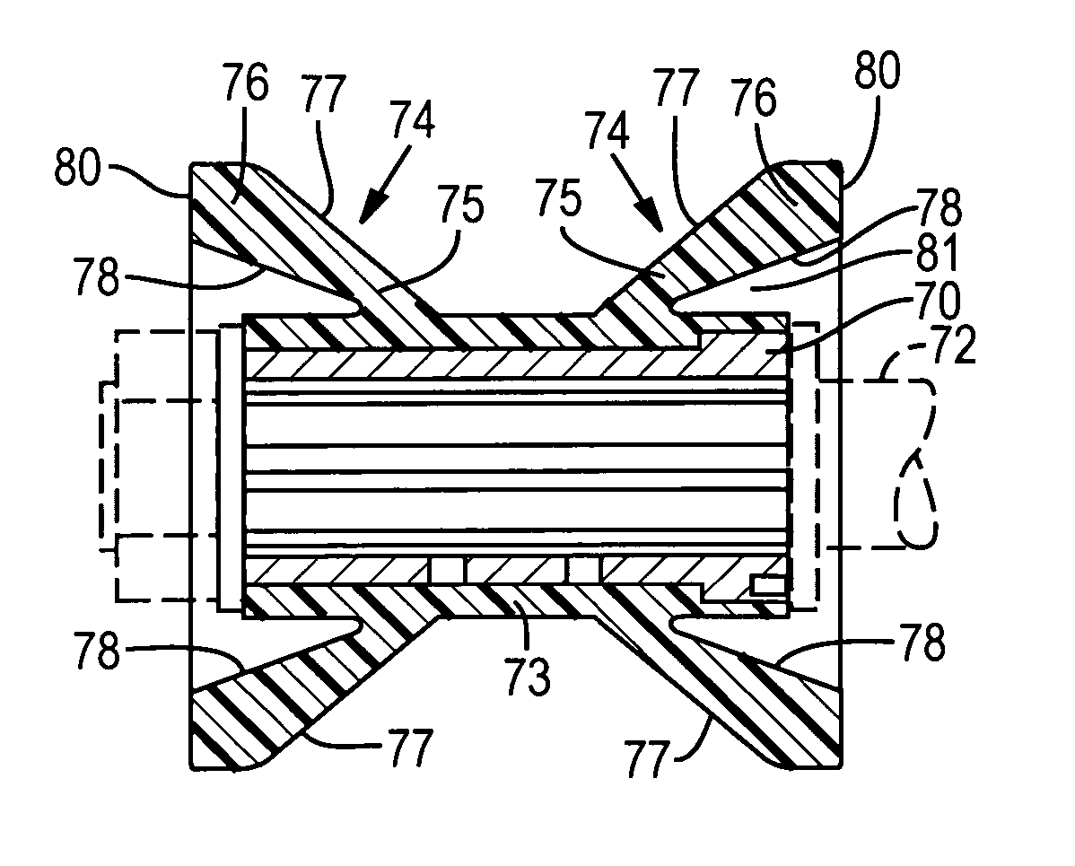
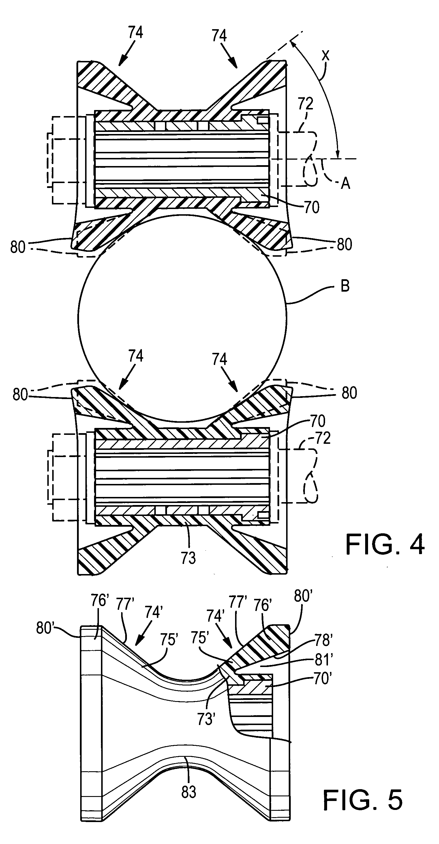
[0013] With attention now to the present roll, a hub is 70 is internally grooved or otherwise provided for driven engagement with a shaft 72. A sleeve at 73, of resilient material, is formed about the hub. End members at 74 of a roll are of generally of conical shape each having inner portions 75 merging with outer portions 76 and jointly prov...


PUM


Abstract

A feed roll for use in conjunction with a machine in a food processing operation. A hub of the roll carries a resilient outer component including a sleeve having conical end members which flex during momentary contact with the article. The surface areas of the flexed end members are adequate to advance the article being processed while avoiding damage to the article.

Description

BACKGROUND OF THE INVENTION [0001] The present invention concerns feed rolls used in commercial enterprises to advance articles along a course during processing of same. [0002] By way of example, in the food processing industry it is a common practice to transfer, in succession, harvested ears of corn along a conveyor path with the objective being the introduction of each ear to a corn cutting machine for separation of kernels from cob. [0003] U.S. Pat. No. 5,830,060, incorporated herein by reference, discloses such a machine. The patented machine has cooperating upper and lower pairs of rolls which receive each husk free ear of corn in sequence and advance same into a housing wherein an orbital cutter blade removes the kernels. The upper and lower pairs of rolls have lugs which frictionally engage the ear kernels. The lugs on existing rolls have angular surfaces resulting in line contact with and the rupturing of some kernels which become waste as damaged kernels are often not util...

Claims


Application Information

Patent Timeline
Patent Type & Authority Applications(United States)
IPC IPC(8): B65G39/06
CPCB65G37/005B65G39/06
Inventor ANDERSON, RONALD L.
Owner ANDERSON RONALD L
Why Eureka
Try Eureka