Optical transmission system

a transmission system and optical transmission technology, applied in the field of optical transmission systems, can solve the problems a large repair cost, and a serious problem, and achieve the effect of effectively monitoring the operating status of raman amplification repeaters

Inactive Publication Date: 2006-09-05
FUJITSU LTD
View PDF16 Cites 29 Cited by
  • Summary
  • Abstract
  • Description
  • Claims
  • Application Information

AI Technical Summary

Benefits of technology

The objective of this patent is to create an optical communication system that can easily detect if there are any problems with its equipment, especially during times when parts of the network may be damaged or fail.

Problems solved by technology

The technical problem addressed in this patent relates to finding ways to prevent loss of monitoring mechanisms in submarine optical transmission systems caused by fiber failures or damages. This issue may occur even though repeated attempts are made to mitigate these risks through various measures like reducing the distance between repeaters and utilizing alternative amplification methods like raman amplification.

Method used


Image

  • Optical transmission system
  • Optical transmission system
  • Optical transmission system

Examples


first embodiment

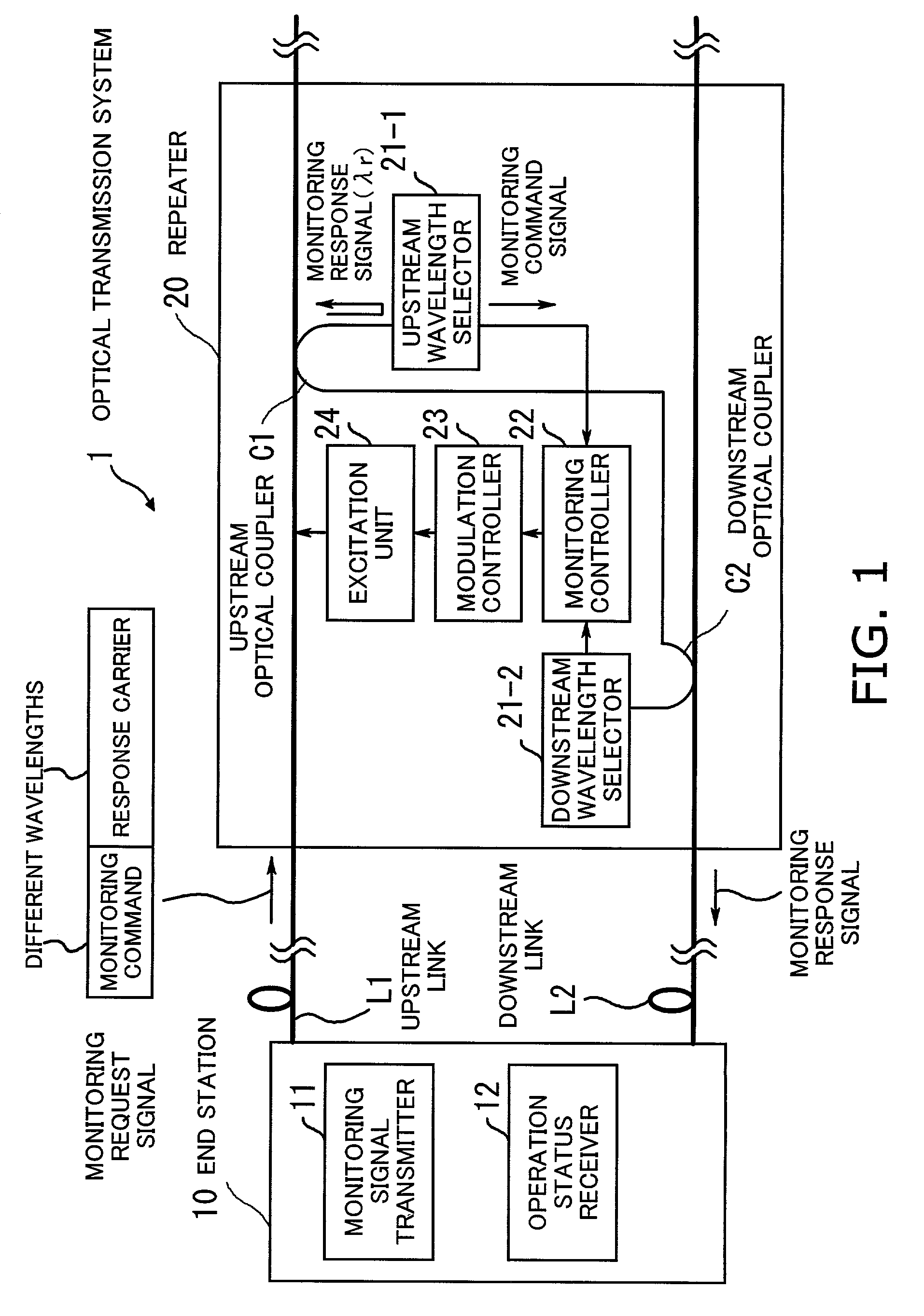
[0072]FIG. 8 is a block diagram of the present invention. The illustrated repeater 20-1 has the following elements: FBGs 21-1 and 21-2, photodiodes PD1 and PD2, laser diodes LD1 and LD2, a supervisory circuit (SV), optical couplers C1 and C2, and WDM couplers Cw1 and Cw2. It is assumed in FIG. 8 that an end station 10 (not shown) is located on the left of the repeater 20-1. When a monitoring request signal is received from the end station 10, this repeater 20-1 operates as follows:[0073](S21) The optical monitoring request signal is split off at the upstream optical coupler C1 and directed to the inside of the repeater 20-1.[0074](S22) The FBG 21-1 allows the monitoring command signal to pass through to the upstream photodiode PD1.[0075](S23) The upstream photodiode PD1 transduces the optical monitoring request signal into an electric signal for delivery to the supervisory circuit SV.[0076](S24) The supervisory circuit SV recognizes the received signal as a monitoring command signal...

fourth embodiment

[0091]FIG. 16 is a block diagram of a repeater 20-4 according to the present invention. This repeater 20-4 differs from the preceding ones in its use of 3-dB couplers C3-1 and C3-2. The first 3-dB coupler C3-1 distributes pump beams from laser diodes LD1 and LD2 to the upstream link L1 and downstream link L2 in their respective backward directions through WDM couplers Cw1 and Cw2. Likewise, the second 3-dB coupler C3-2 distributes pump beams from laser diodes LD3 and LD4 to the upstream link L1 and downstream link L2 in their respective forward directions through WDM couplers Cw1a and Cw2a. This means that the illustrated repeater 20-4 pumps both forward and backward, thus performing two-way-pumped Raman amplification.

fifth embodiment

[0092]FIG. 17 is a block diagram of a repeater 20-5 according to the present invention. This repeater 20-5 differs from the preceding ones in its use of directional isolators. One isolator ISO1 is placed between the WDM coupler Cw1 and optical coupler C1 on the upstream link L1. Another isolator ISO2 is placed between the WDM coupler Cw2 and optical coupler C2 on the downstream link L2. These upstream and downstream isolators ISO1 and ISO2 prevent optical signals from propagating in unintended directions, thus suppressing multiple-reflection degradation. This feature of the illustrated repeater 20-5 ensures stable operation of optical amplifiers.


PUM


Abstract

An optical transmission system capable of monitoring the operating status of Raman-amplifier repeaters even when an optical transmission line is partly disrupted by a fiber failure. An end station sends a monitoring command signal to request a particular repeater to report its operating status, together with a response carrier wave for use in that reporting. With their different wavelengths, an upstream wavelength selector in the repeater selectively passes the monitoring command signal while reflecting back the response carrier wave. Responsive to the command, a monitoring controller creates a response message containing operating status information. An excitation unit performs Raman amplification with a pump beam modulated by a modulation controller, so that the response message be superimposed on the response carrier wave propagating on the upstream link. The resulting monitoring response signal is routed from the upstream wavelength selector to a downstream optical coupler and sent back to the requesting end station.

Description


Claims


Application Information

Patent Timeline
Owner FUJITSU LTD
Why Eureka
Try Eureka