
Contoured housing for an implantable medical device

a medical device and housing technology, applied in the field of housings for implantable medical devices, can solve the problems of human, more excavation than is required, and limiting the area of the housing, so as to achieve the effect of facilitating the placement of implantable devices in other locations in the body such as the arms and legs

Active Publication Date: 2006-09-05
WILSON GREATBATCH LTD
View PDF56 Cites 64 Cited by
  • Summary
  • Abstract
  • Description
  • Claims
  • Application Information

AI Technical Summary

Benefits of technology

[0002]Implantable medical devices include hearing-assist devices, artificial hearts, neurostimulators, drug pumps, cardiac pacemakers, cardiac defibrillators and heart-assist devices. Conventionally, these devices include a housing with planar side walls, such as in a prismatic design. However, the shape of the housing limits the areas in a body, human or otherwise, in which the device can be implanted. If an area of the body, such as the skull, must be excavated, a conventional prismatic housing requires that the cavity be shaped to fit the planar prismatic design. This may necessitate more excavation than is required if the housing is contoured to fit the patient's anatomy. Furthermore, the planar design of current prismatic housings makes it more difficult for implantable devices to be placed in other locations in the body such as the arms and legs.
[0003]Accordingly, there is a need for a housing for an implantable medical device that is shaped or contoured to more closely fit the curved shape of a body. This facilitates implanting assist devices in areas where it is difficult, if not impossible, to place conventionally shaped devices. Furthermore, not only does a contoured shaped housing aid in the placement of assist devices into the body where they could not previously be placed, but it also helps in placing them in areas of the body where they are frequently used, but without undo excavation.

Problems solved by technology

However, the shape of the housing limits the areas in a body, human or otherwise, in which the device can be implanted.
This may necessitate more excavation than is required if the housing is contoured to fit the patient's anatomy.
Furthermore, the planar design of current prismatic housings makes it more difficult for implantable devices to be placed in other locations in the body such as the arms and legs.

Method used


Image

  • Contoured housing for an implantable medical device
  • Contoured housing for an implantable medical device
  • Contoured housing for an implantable medical device

Examples


Embodiment Construction

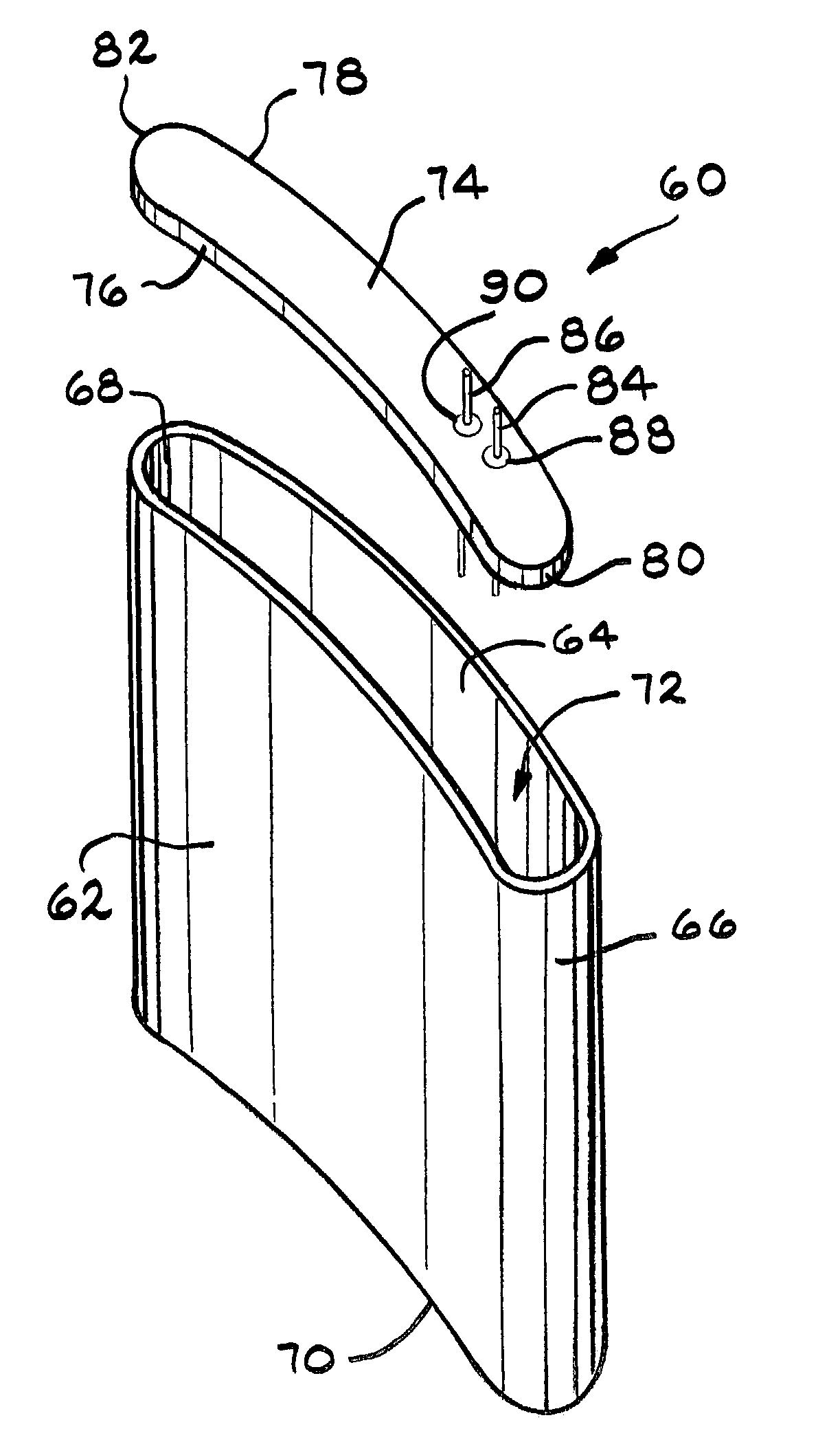
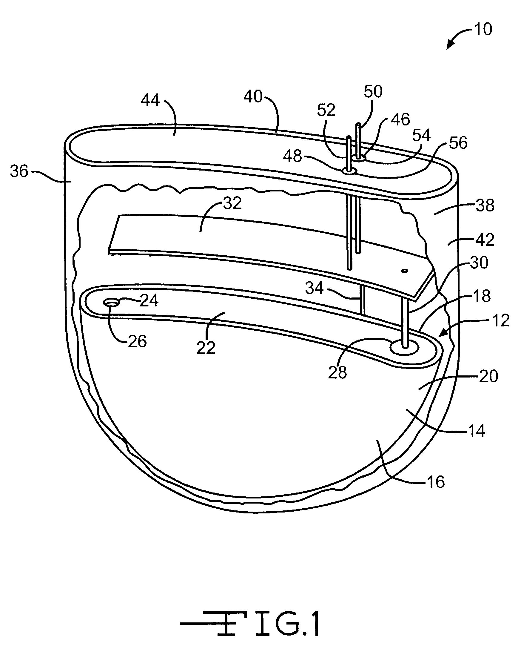
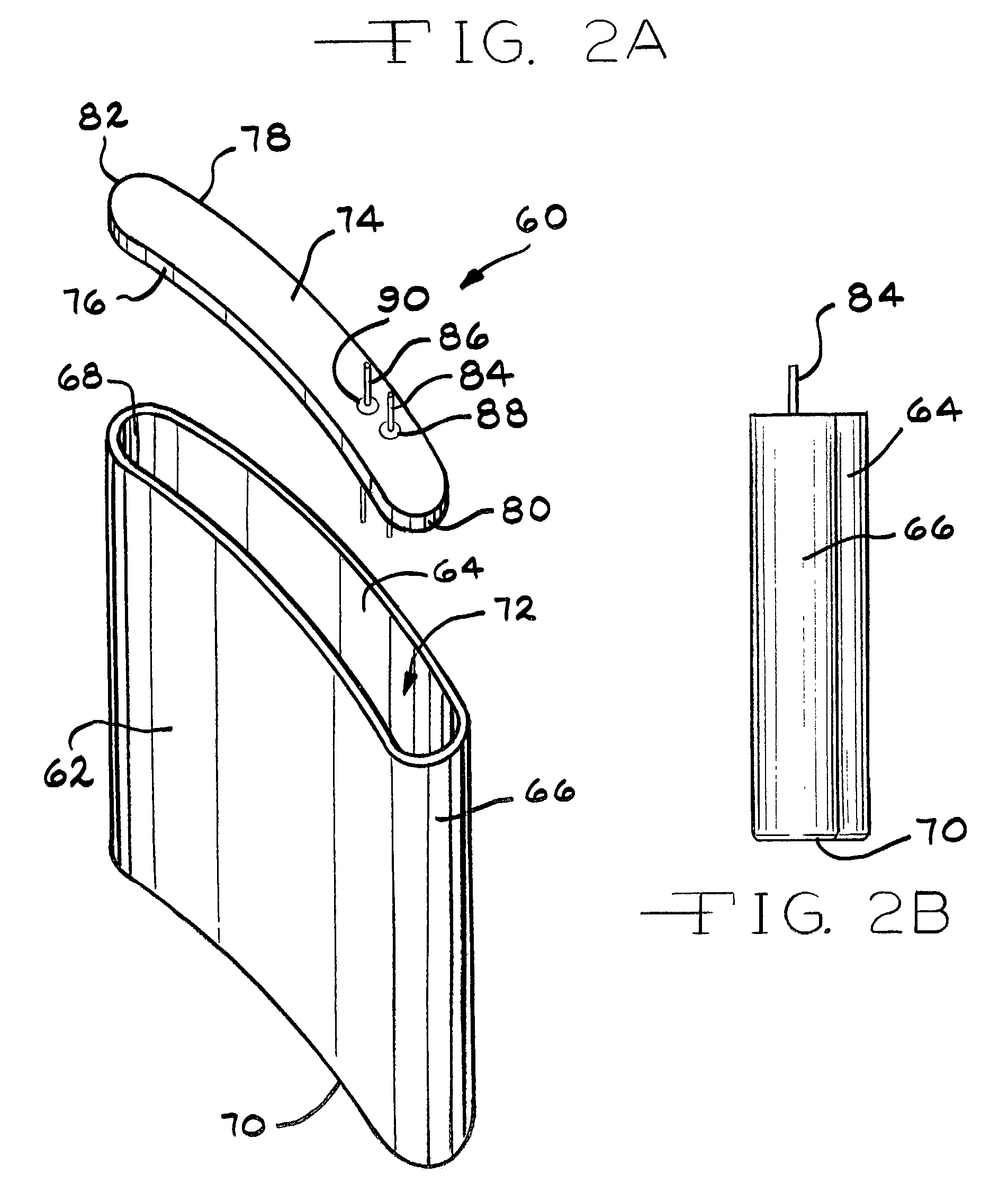
[0015]FIG. 1 shows a representative implantable device 10 powered by an implantable electrochemical cell 12. Both the device 10 and the cell 12 are comprised of housings or casings having contoured side walls according to the present invention The housings and casings of this invention are preferably of conductive materials selected from nickel, aluminum, stainless steel, mild steel, tantalum and titanium.

[0016]The cell 12 is comprised of a casing 14 having spaced apart and opposed major front and back side walls 16 and 18. The walls 16, 18 each have a generally semicircular shape with a planar upper edge. The side walls 16, 18 extend to and meet with a semicircular intermediate end wall 20 that curves to meet them along their entire radial perimeter. The side walls 16, 18 and end wall 20 form the casing as a unitary, deep drawn member. Both of the major front and back side walls 16, 18 have a curved shape of a continuous radius deflecting in a similar direction and extending from t...


PUM

PropertyMeasurementUnit
electrical energyaaaaaaaaaa
curvatureaaaaaaaaaa
distanceaaaaaaaaaa

Abstract

An implantable medical device having opposed major sidewalls of contoured shape closely fits the curved shape of a body. The contoured major sidewalls can have a curved shape of a continuous radius with the major sidewalls deflecting in a similar direction. Alternatively, the major sidewalls can have a curved shape corresponding to more than one radius. The device housing is either deep drawn or includes two clam shells that are secured together.

Description

CROSS-REFERENCE TO RELATED APPLICATIONThis application claims priority based on provisional application Serial No. 60 / 306,647, filed Jul. 19, 2001.BACKGROUND OF THE INVENTION[0001]The present invention relates to implantable medical devices and, more particularly, to housings for implantable medical devices. The housings have contoured surfaces to more closely conform to body contours. This facilitates implantation in areas of a body that were heretofore not possible because of geometrical limitations.SUMMARY OF THE INVENTION[0002]Implantable medical devices include hearing-assist devices, artificial hearts, neurostimulators, drug pumps, cardiac pacemakers, cardiac defibrillators and heart-assist devices. Conventionally, these devices include a housing with planar side walls, such as in a prismatic design. However, the shape of the housing limits the areas in a body, human or otherwise, in which the device can be implanted. If an area of the body, such as the skull, must be excavate...

Claims


Application Information

Patent Timeline
Patent Type & Authority Patents(United States)
IPC IPC(8): A61N1/372A61F11/00A61M1/10A61M1/12A61M31/00A61N1/375H01M4/48H01M4/485H01M4/58H01M4/583H01M6/10H01M6/16H01M10/0525H01M10/36H01M50/103H01M50/119H01M50/147H01M50/202H01M50/224H01M50/247H01M50/271H01M50/298H01M50/591H01M50/627H04R25/00
CPCA61N1/375H01M2/0202H01M2/027H01M2/0275H01M2/0285H01M2/1022H01M2/361Y02E60/122H01M2/0404H01M2/36H01M4/48H01M4/485H01M4/583H01M6/10H01M6/16H01M10/0525H01M2002/0205A61N1/3758A61N1/37512Y02E60/10H01M50/545H01M50/147H01M50/247H01M50/119H01M50/202H01M50/271H01M50/591H01M50/224H01M50/103H01M50/298H01M50/627
Inventor PROBST, JOSEPH M.WUTZ, PHILIP S.
Owner WILSON GREATBATCH LTD
Learn More