
Structure health monitoring system and method

a technology for health monitoring and structure, applied in the direction of testing/monitoring control systems, instruments, nuclear elements, etc., can solve the problems of not processing sensor data over time, affecting the safety of the structure, and the prior art does not include a “self-contained” structure health monitoring system. , to achieve the effect of reducing the ownership cost of an aircraft, a boat or a vehicle, and improving safety margins

Active Publication Date: 2006-09-05
HONEYWELL INT INC
View PDF6 Cites 58 Cited by
  • Summary
  • Abstract
  • Description
  • Claims
  • Application Information

AI Technical Summary

Benefits of technology

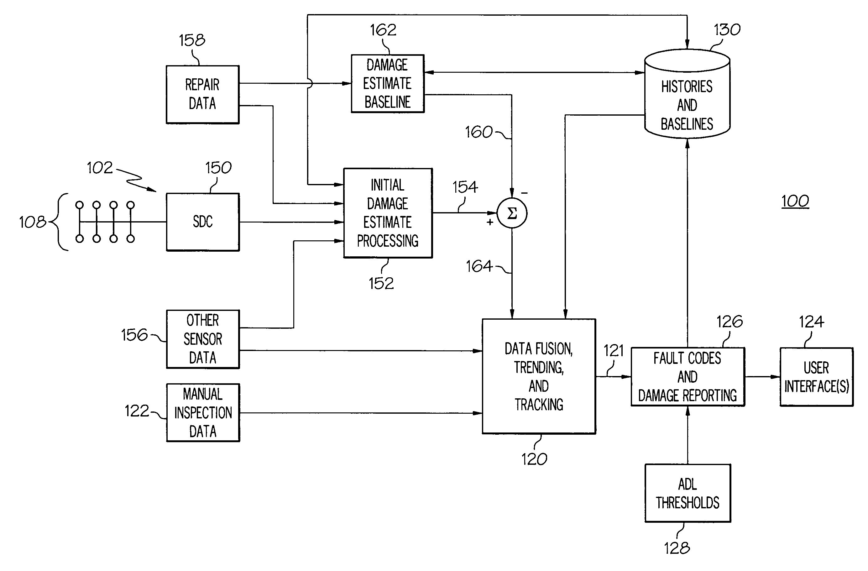
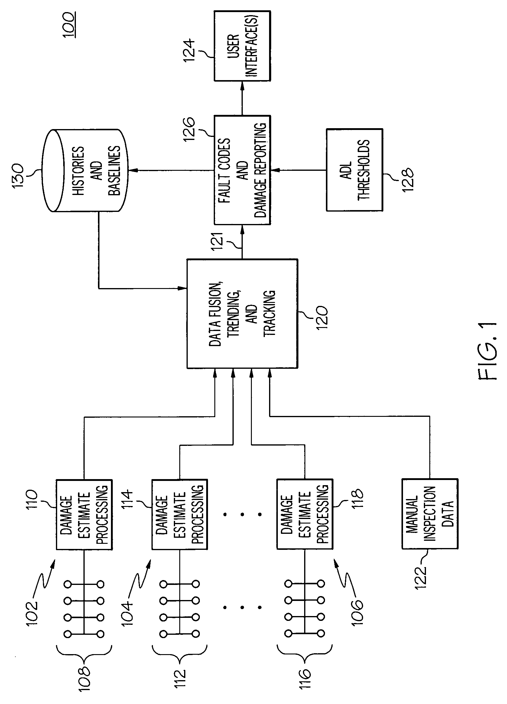
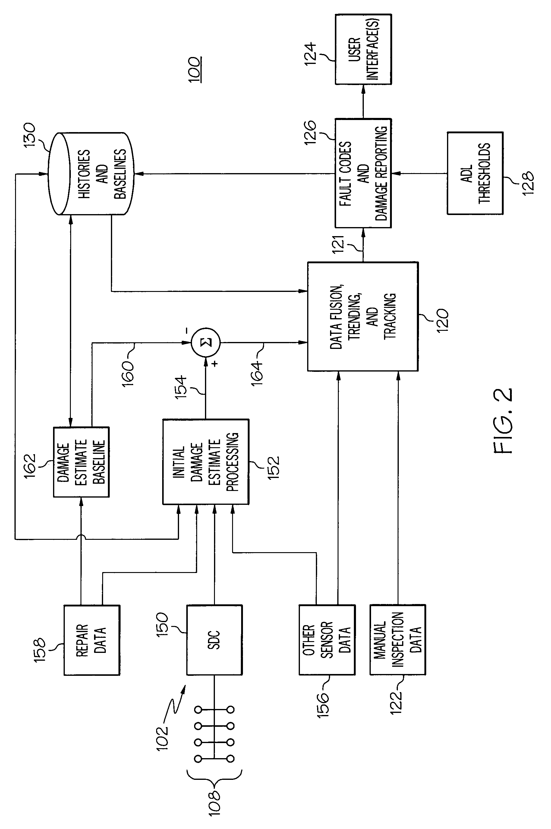
[0004]An onboard structural health monitoring system according to the invention can further improve safety margins and reduce the ownership cost of an aircraft, boat, or vehicle. The system can eliminate manual structural inspections and provide a capability for prognostic determination of remaining lifetime and maintenance scheduling. The above and other aspects of the invention may be carried out in one form by a method for monitoring structural health of an apparatus. The method involves obtaining sensor data indicative of the structural integrity of a component of the apparatus, processing the sensor data to obtain an initial damage estimate for the component, generating a final damage estimate in response to the initial damage estimate and in response to a damage estimate baseline, and formatting the final damage estimate into at least one displayable damage representation.

Problems solved by technology

Structural inspections of commercial aircraft are usually performed manually and, therefore, can be labor intensive and costly, especially if a large fleet of aircraft is being maintained.
Such systems, however, do not process the sensor data over time for purposes of trending, reporting, forecasting remaining lifetime, and scheduling maintenance.
Furthermore, the prior art does not include a “self-contained” onboard structure health monitoring system that can be deployed in an aircraft.

Method used


Image

  • Structure health monitoring system and method
  • Structure health monitoring system and method
  • Structure health monitoring system and method

Examples


Embodiment Construction

[0011]The following detailed description is merely exemplary in nature and is not intended to limit the invention or the application and uses of the invention. Furthermore, there is no intention to be bound by any expressed or implied theory presented in the preceding technical field, background, brief summary or the following detailed description.

[0012]The invention may be described herein in terms of functional and / or logical block components and various processing steps. It should be appreciated that such block components may be realized by any number of hardware, software, and / or firmware components configured to perform the specified functions. For example, an embodiment of the invention may employ various integrated circuit components, e.g., memory elements, digital signal processing elements, logic elements, look-up tables, or the like, which may carry out a variety of functions under the control of one or more microprocessors or other control devices. In addition, those skil...


PUM


Abstract

A structure health monitoring (“SHM”) system according to the invention can be deployed in an onboard environment, such as an aircraft, to provide an ongoing damage assessment of structural components on the aircraft. The SHM system reduces or eliminates time consuming and costly manual inspections of aircraft. The SHM system can leverage known sensor technologies to collect sensor data indicative of the structural health of the monitored components. The sensor data is processed and baselined with sensor feature baselines and damage estimate baselines to provide an accurate final damage estimate for the monitored component. The final damage estimate can be further processed or formatted for compatibility with aircraft maintenance systems.

Description

TECHNICAL FIELD[0001]The present invention generally relates to structure health monitoring systems, and more particularly relates to a structure health monitoring system configured for deployment in an aircraft.BACKGROUND[0002]Certain vehicles, buildings, watercraft, and other structures may be subjected to periodic physical inspections that monitor the health of various components within the structures. For example, commercial aircraft may be routinely inspected to confirm, for example, structural integrity. Structural inspections of commercial aircraft are usually performed manually and, therefore, can be labor intensive and costly, especially if a large fleet of aircraft is being maintained. The prior art includes a variety of sensor systems designed to obtain data indicative of potential structural defects. Such systems, however, do not process the sensor data over time for purposes of trending, reporting, forecasting remaining lifetime, and scheduling maintenance. Furthermore,...

Claims


Application Information

Patent Timeline
Patent Type & Authority Patents(United States)
IPC IPC(8): G06F11/30G01B3/44
CPCG05B23/0283G05B23/0213
Inventor GORINEVSKY, DIMITRYGORDON, GRANT A.NUTARO, JOSEPH
Owner HONEYWELL INT INC
Learn More