Magnetically Enhanced Thin Film Coating Method and Apparatus

a technology of enhanced thin film and coating method, applied in the direction of coatings, chemical vapor deposition coatings, electric discharge tubes, etc., can solve the problems of affecting the top surface of the workpiece, increasing the difficulty of hollow glow discharge, and increasing the difficulty of sustaining the hollow glow discharge. , to achieve the effect of enhancing the glow discharge, efficiently deposition functional layer, and high aspect ratio

Inactive Publication Date: 2012-12-13
GE YI +1
View PDF20 Cites 9 Cited by
  • Summary
  • Abstract
  • Description
  • Claims
  • Application Information

AI Technical Summary

Benefits of technology

[0031]The present invention includes, at least, a permanent magnet array assembly embodied on a PECVD system for internal wall coating of work piece with high aspect ratio and / or complicated internal structures such as pipe and tube. The method includes: isolate the work piece and use it as effective vacuum chamber; input gas precursor and / or gas mixture for designed internal coating layer structure; apply either pulse DC or RF energy and use the permanent magnet array assembly to enhance the glow discharge in the whole or only certain portion of the work piece; to efficiently deposition functional layer(s) on the internal wall of the work piece.
[0032]The design of adding the permanent magnet arrays assembly in the present apparatus is of importance. Firstly, the magnetic field restricts the path of free electron within the glow discharge and effectively increase the efficiency of ionization within the glow discharge and allow the sustain of the glow discharge under high gas pressure of precursor (or process gas mixture) with the possibility of sustain glow discharge even under atmosphere pressure to allow high rate deposition and lower process temperature. The sustaining of the glow discharge at lower vacuum or even at atmosphere pressure reduce overall cost of ownership of the apparatus while still retaining the quality of the internal coating with higher deposition rate. Secondly, the magnet array assembly can be rotated or oscillate around the longer axial of the work piece with dwell time optimized for special purpose. For example, the dwell time can be optimized for uniformity coating thickness along the work piece in one case, while in the other case, the deposition thickness can be specified at particular location for the purpose of enhance the functionality and performance of the work piece.
[0033]In this invention, there are two types of designs for the permanent magnet array assembly: one is implemented outside of the work piece; the other is put inside of the work piece. The type of permanent magnet array assembly for use outside of the work piece is particularly useful for the work piece with small internal wall diameter such as the capillary tube used within the medical instruments or the microfluidic devices. For the work piece with large enough internal wall diameter, the magnet array assembly design for the internal use could be better. Of course, when the situation is allowed, both types of the permanent magnet array assemblies can be implemented at the same time.

Problems solved by technology

This method can only affect the top surface of the work piece, and the treated depth is generally believed to be too thin for many applications.2. Functional coating the surface of a work piece.
However, when the tube diameter becomes even smaller and the length becomes even longer, it is getting more difficult to sustain the hollow glow discharge.
However, the tube can only be coated one section at a time due to the limitation of localized plasma generated only at the coil location.

Method used


Image

  • Magnetically Enhanced Thin Film Coating Method and Apparatus
  • Magnetically Enhanced Thin Film Coating Method and Apparatus
  • Magnetically Enhanced Thin Film Coating Method and Apparatus

Examples


Embodiment Construction

[0043]The following description is provided in the context of particular applications and the details, to enable any person skilled in the art to make and use the invention. However, for those skilled in the art, it is apparent that various modifications to the embodiments shown can be practiced with the generic principles defined here, and without departing the spirit and scope of this invention. Thus, the present invention is not intended to be limited to the embodiments shown, but is to be accorded the widest scope consistent with the principles, features and teachings disclosed here.

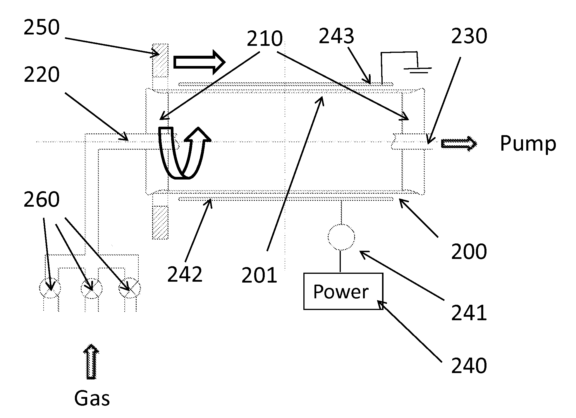
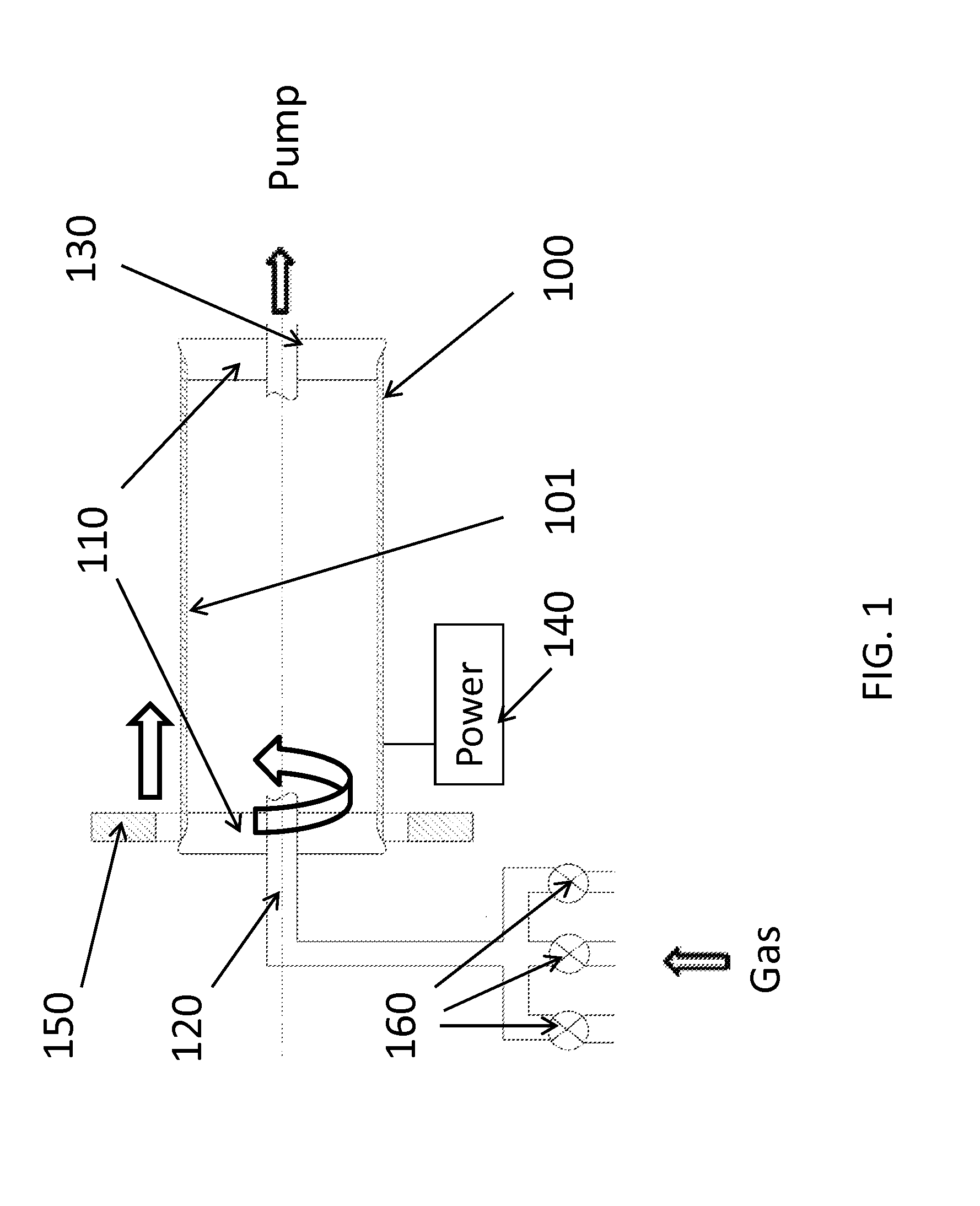
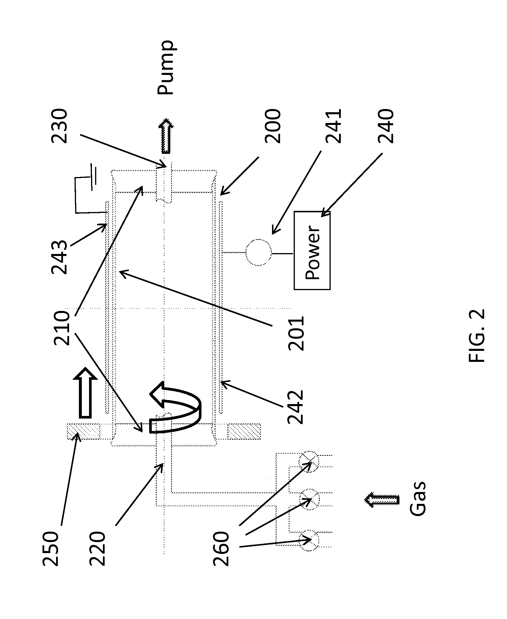
[0044]The present invention relates to method and apparatus design to facilitate the disposition of the functional coating on the internal wall of the work piece with particularly emphasis on implementing the permanent magnet array assembly to enhance the glow discharge during PECVD coating. Depending on the size of the permanent magnet array assembly relative to the work piece, the glow discharge ca...


PUM

PropertyMeasurementUnit
magnetic fieldaaaaaaaaaa
conductiveaaaaaaaaaa
non-conductiveaaaaaaaaaa

Abstract

Methods and apparatuses for implementing magnetic field to assist PECVD to locally or globally coat the internal surface of the work piece are presented. Several permanent magnet assembly designs have been presented to provide efficient and effective magnetic field inside the work piece, which acts partially as the working chamber. The magnet assembly generates magnetic flux inside the working chamber, which increases the efficiency of PECVD process, enable PECVD process under higher gas pressure and to improve the uniformity, deposition rate, better adhesion and reduce the process temperature.

Description

REFERENCE CITEDUs Patent Documents[0001]1) K. Baba et.al, Surface and Coating Technology, Vol. 74-75, 1995, P292.[0002]2) Hitomi Yamaguchi, et.al, J. Manufacturing Science and Engineering, Vol. 129, 2007, P885.[0003]3) Hiroyuki Yoshiki, et.al, J. Vac. Sci. A 26(3), May / June 2008, P338;[0004]4) Hiroyuki Yoshiki, et.al, Vacuum 84 (2010)559;[0005]5) Shamim M. Malik, et.al, J. Vac. Sci. A 15(6), November / December 1997, P2875;[0006]6) R. Hytry, et.al, Surface and Coating Technology, 74-75 (1995)43;[0007]7) R. Hytry, et.al, J. Vac. Sci. A 11(15), September / October 1993, P2508;[0008]8) U.S. Pat. No. 4,335,677;[0009]9) U.S. Pat. No. 3,974,306;[0010]10) U.S. Pat. No. 5,567,268;[0011]11) U.S. Pat. No. 5,585,176;[0012]12) U.S. Pat. No. 5,902,675;[0013]13) U.S. Pat. No. 6,436,252;[0014]14) U.S. Pat. No. 6,767,436;[0015]15) U.S. Pat. No. 7,052,736;[0016]16) U.S. Pat. No. 7,629,031;[0017]17) U.S. Pat. No. 7,608,151;[0018]18) U.S. Pat. No. 5,224,441.FIELD OF INVENTION[0019]The invention is related...

Claims


Application Information

Patent Timeline
Patent Type & Authority Applications(United States)
IPC IPC(8): C23C16/503C23C16/507
CPCC23C16/045H01J37/32669H01J37/32394C23C16/515
Inventor YI, GETANG, YUNJUN
Owner GE YI
Why Eureka
Try Eureka