Spray cooling system for transverse thin-film evaporative spray cooling

a cooling system and evaporative spray technology, applied in the direction of domestic cooling apparatus, lighting and heating apparatus, semiconductor/solid-state device details, etc., can solve the problems of hot spots, component overheating, and difficult removal of unwanted hea

Active Publication Date: 2006-09-12
PARKER INTANGIBLES LLC
View PDF16 Cites 30 Cited by
  • Summary
  • Abstract
  • Description
  • Claims
  • Application Information

AI Technical Summary

Problems solved by technology

The smaller components and packaging makes the removal of the unwanted heat more difficult.
If there is too little flow or coverage of coolant, the liquid layer covering the electronic component will dry out and cause the component to overheat because vapor forced convection will not typically provide sufficient heat transfer.
If the flow of coolant to the component is too great, the device will become flooded and may produce hot spots, insufficient cooling and / or failure, because the vapor created from the evaporation may become trapped between the excessive fluid and the impingement surface of the electronic component.
This will normally reduce the cooling efficiency.
Vapor generated at the surface of the component which receives too much coolant cannot escape effectively and could result in a boiling heat transfer failure mode generally referred to as burnout.

Method used


Image

  • Spray cooling system for transverse thin-film evaporative spray cooling
  • Spray cooling system for transverse thin-film evaporative spray cooling
  • Spray cooling system for transverse thin-film evaporative spray cooling

Examples


Embodiment Construction

[0031]Many of the fastening, connection, manufacturing and other means and components utilized in this invention are widely known and used in the field of the invention described, and their exact nature or type is not necessary for an understanding and use of the invention by a person skilled in the art or science; therefore, they will not be discussed in significant detail. Furthermore, the various components shown or described herein for any specific application of this invention can be varied or altered as anticipated by this invention and the practice of a specific application or embodiment of any element may already be widely known or used in the art or by persons skilled in the art or science; therefore, each will not be discussed in significant detail.

[0032]The terms “a”, “an”, and “the” as used in the claims herein are used in conformance with long-standing claim drafting practice and not in a limiting way. Unless specifically set forth herein, the terms “a”, “an”, and “the”...


PUM


Abstract

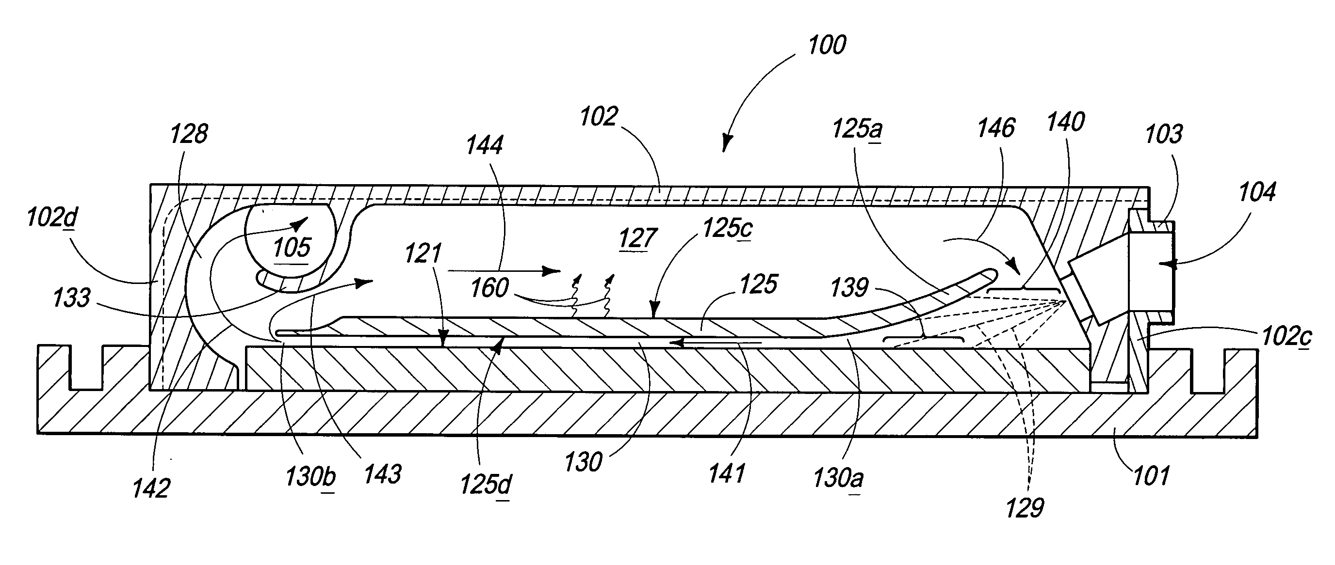
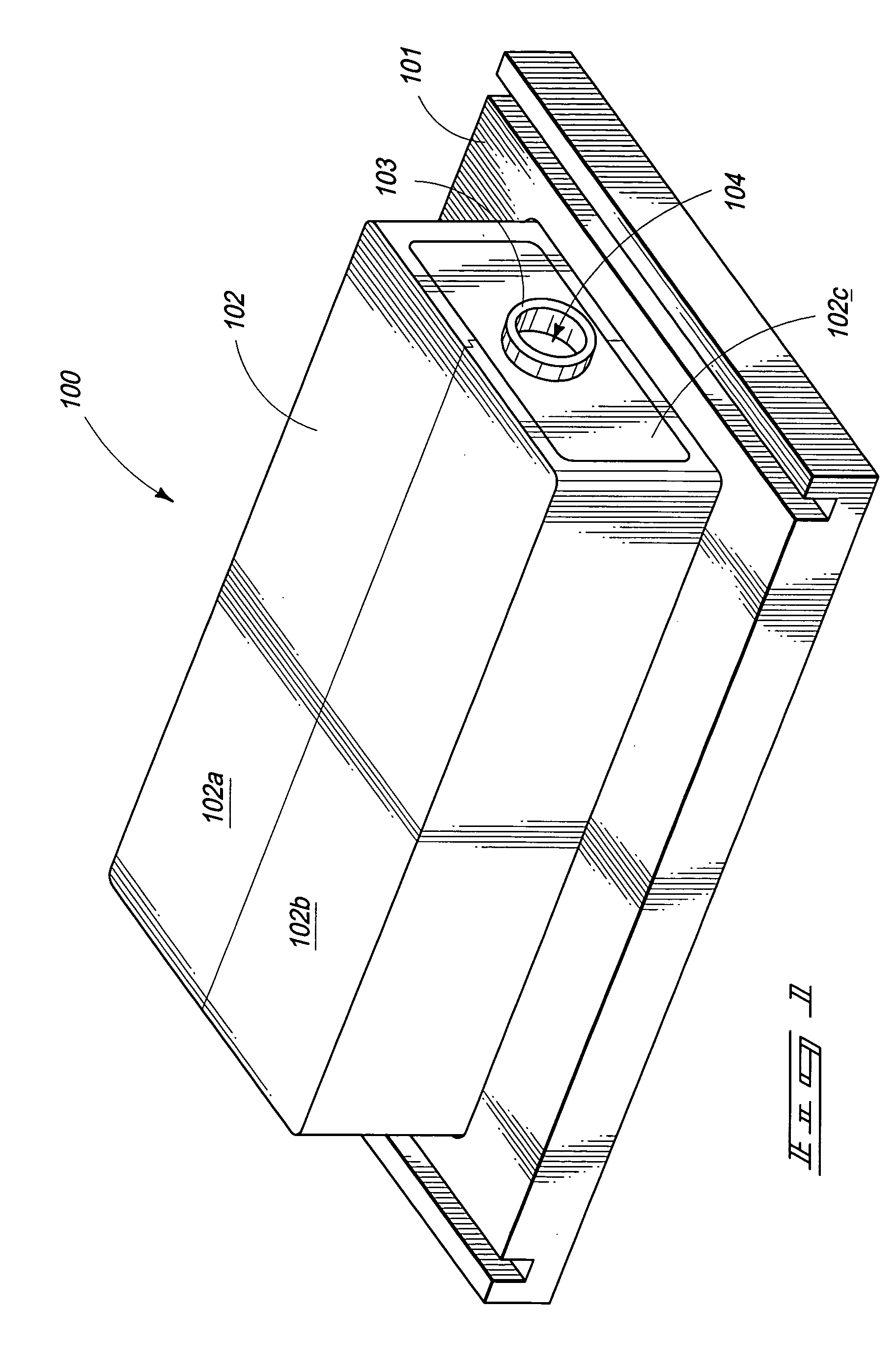
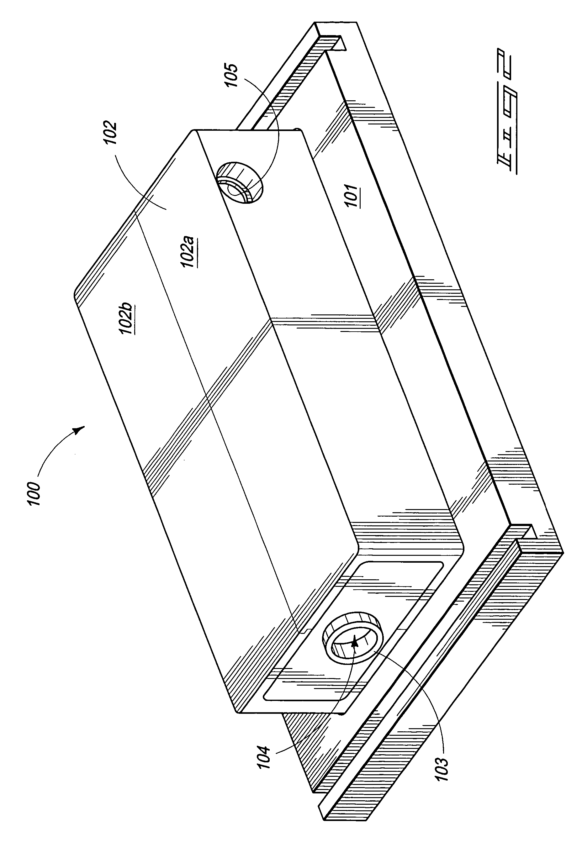
A spray cooling system for transverse evaporative spray cooling in a narrow gap which may generally include a mixing zone, a converging zone, a cooling conduit, and a re-circulation conduit. The spray cooling system in some of its embodiments, provides among other things, a feed system for narrow gap evaporative spray cooling, a method for reducing the pressure gradient across the surface from which heat is to be transferred and a housing system which utilizes a baffle to separate the cooling conduit from a re-circulation conduit and to re-circulate vapor to the entry of the cooling conduit.

Description

TECHNICAL FIELD[0001]This invention relates to an evaporative spray cooling system for transverse evaporative thin-film spray cooling of electronic components.BACKGROUND OF THE INVENTION[0002]As electronic components continue to advance and are made more powerful, they tend to produce more and more undesirable heat which is preferably removed. This has created a growing need for higher capacity cooling systems to remove heat from all or a portion of the electronic components.[0003]As the trend is to make electronic components more powerful, there is also an increasing push to reduce the size of the electronic components, and the packaging of the electronic components. The smaller components and packaging makes the removal of the unwanted heat more difficult.[0004]In some applications, direct impingement thin-film evaporative spray cooling is preferred in order to provide sufficient cooling, whereas in other applications spray cooling is desired to reduce the overall package or housi...

Claims


Application Information

Patent Timeline
Patent Type & Authority Patents(United States)
IPC IPC(8): F28C1/00
CPCF25B39/02H01L23/4735F25B2339/021H01L2924/0002H01L2924/00
Inventor TILTON, CHARLES L.
Owner PARKER INTANGIBLES LLC
Why Eureka
Try Eureka