Compact spray cooling module

a technology of spray cooling and spray cooling module, which is applied in the direction of cooling/ventilation/heating modification, semiconductor device details, semiconductor/solid-state device details, etc., can solve the problems of increasing the size and manufacturing cost of spray cooling system, unable to meet the heat dissipation requirement of current semiconductor device of high heat, and unable to remove the heat generated by the device, etc., to achieve the effect of low power consumption

Inactive Publication Date: 2007-06-14
IND TECH RES INST
View PDF21 Cites 30 Cited by
  • Summary
  • Abstract
  • Description
  • Claims
  • Application Information

AI Technical Summary

Benefits of technology

[0006] In view of the disadvantages of prior art, the primary object of the present invention is to provide a compact spray cooling module of low power consumption capable of generating atomized cooling liquid by a piezoelectric unit.
[0008] It is yet another object of the invention to provide a compact spray cooling module, which combines a nebulizer, a circulation circuit, a storage tank and a condenser to form a small and integrated module.
[0009] To achieve the above objects, the present invention provides a compact spray cooling module, which comprises: a storage tank, for storing a cooling liquid; a spray chamber, connected to a heat source; a nebulizer, arranged at the top portion of the spray chamber, further comprising a piezoelectric plate and a micro-nozzle plate with a plurality of micro-nozzles disposed thereon; and a media of liquid transportation ability; wherein the media has the capability of transporting the cooling liquid from the storage tank to the nebulizer by capillary attraction for enabling the cooling liquid to be atomized by the nebulizer and sprayed into the spray chamber for absorbing and removing thermal energy from the heat source.
[0015] Preferably, fins or fans can be arranged on the shell at the position corresponding to the condense chamber for enhancing the heat to be removed from the evaporated cooling liquid flowing in the condense chamber while condensing the same.

Problems solved by technology

With the advent of semiconductor devices having increasingly large component densities, the removal of heat generated by the devices has become an increasingly challenging technical issue.
Generally, semiconductor devices and their associated components are cooled by natural or forced air convection which, because of the relatively poor thermal capacitance and heat transfer coefficients of air, is no longer capable of satisfying the heat dissipating requirement of current semiconductor devices of high heat flux.
However, the pump used by the spray cooling system disclosed in U.S. Pat. No. 6,205,799 for assisting the circulation of the cooling liquid is going to cause the size and the manufacturing cost of the spry cooling system to increase.
Moreover, the nebulizer of the spray cooling system disclosed in U.S. Pat. No. 6,205,799 employs a nozzle design similar to that of a ink-jet print head which generate micro droplets by heating the cooling liquid, that the thermal ink-jet type of nebulizer will require comparatively higher power consumption.
Except for the aforesaid spray cooling system, the apparatus for spray cooling an electronic module as disclosed in U.S. Pat. No. 5,687,577 also utilizes a pump as the power source of circulation, so that it is also suffer the same disadvantages of large volume and high cost.

Method used


Image

  • Compact spray cooling module
  • Compact spray cooling module
  • Compact spray cooling module

Examples


Embodiment Construction

[0023] For your esteemed members of reviewing committee to further understand and recognize the fullfilled functions and structural characteristics of the invention, several preferable embodiments cooperating with detailed description are presented as the follows.

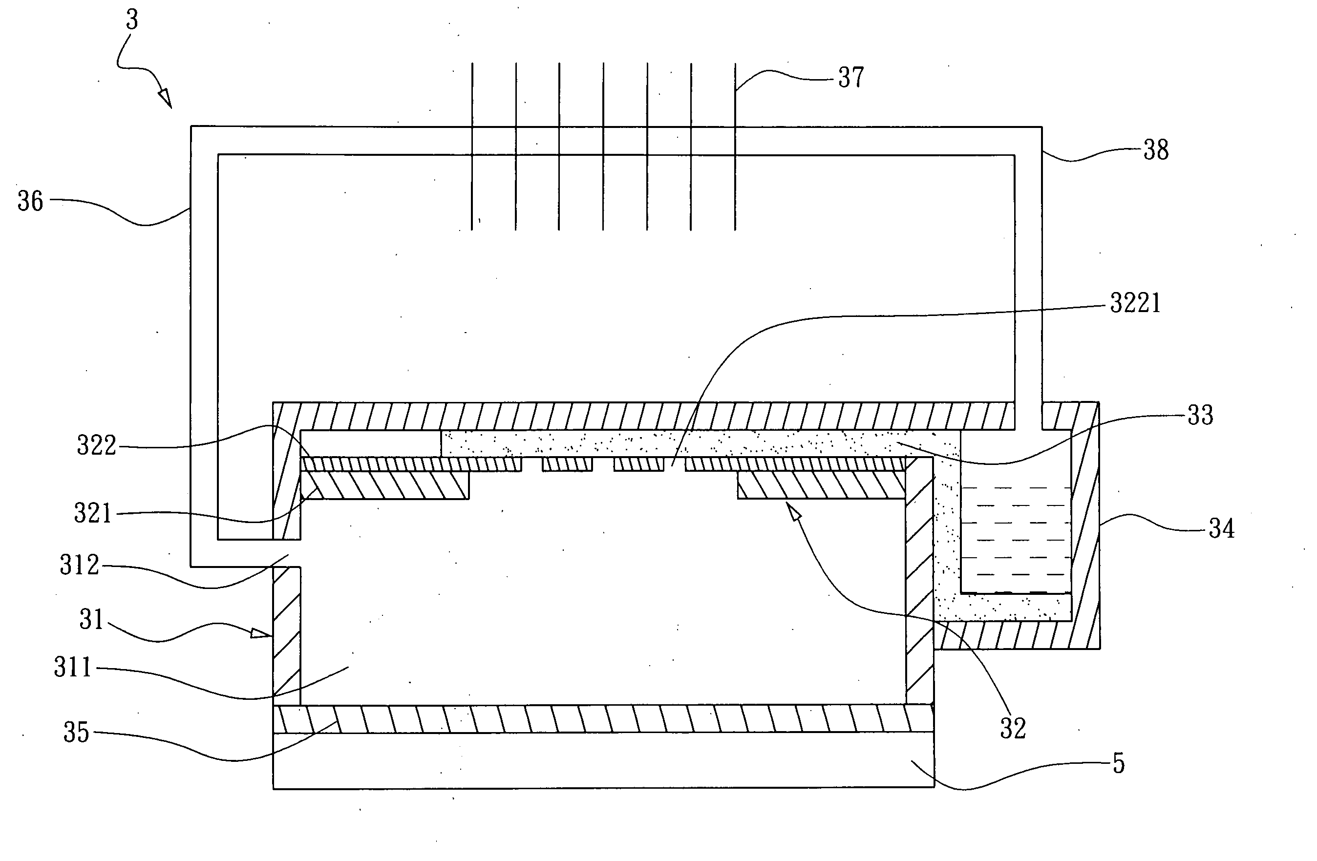
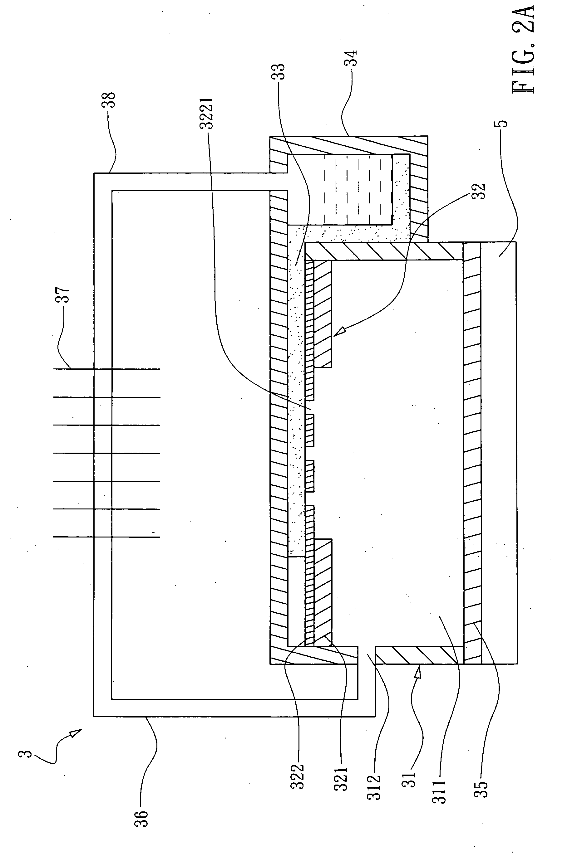
[0024] Pleased refer to FIG. 2A, which is a schematic representation of a spray cooling module according to a first preferred embodiment of the invention. The spray cooling module 3 shown in FIG. 2A is comprised of a spray chamber 31, a storage tank 34, a nebulizer 32 and a media of liquid transportation ability 33. The spray chamber is a hollow structure of specific volume, which encloses a space 311 to be sprayed by atomized cooling liquid. Preferably, the bottom of the spray chamber 31 is formed by a heat-absorbing plate 35, which is abutted upon a heat source 5 by a surface thereof for absorbing heat therefrom and another surface thereof to be impinged by the atomized cooling liquid of the spray chamber. The heat-absor...


PUM


Abstract

A compact spray cooling module is presented, which comprises: a storage tank, a spray chamber, a nebulizer, and a media of liquid transportation ability. The storage tank is used for storing a cooling liquid, and the spray chamber is connected to a heat source. Moreover, there is a nebulizer lay on the spray chamber, whereas the nebulizer is comprised of a piezoelectric plate and a micro-nozzle plate. The micro-nozzle plate has a large number of micro-nozzle disposed on it. Furthermore, the media located between the storage tank and the spray chamber has the capability of transporting the cooling liquid from storage tank to spray chamber by capillary attraction for the purpose of nebulizing the cooling liquid. Taking advantage of the latent heat from liquid phase change, the nebulized cooling liquid sprayed to the bottom of the spraying chamber can dissipate the heat generated from the heat source rapidly. Moreover, the cooling module of the invention can combine with a condenser and a transportation piping system to form a compact and closed spray cooling module.

Description

FIELD OF THE INVENTION [0001] The present invention relates to a heat dissipating apparatus, and more particularly, to a compact spray cooling module capable of utilizing the vibrations generated from a piezoelectric unit thereof to break the surface tension of a cooling liquid while the cooling liquid is guided to be disposed on a piezoelectric unit for enabling the spray cooling module to nebulize the cooling liquid continuously and thus to be used for dissipating heat from a heat source as the nebulized cooling liquid is evaporating. BACKGROUND OF THE INVENTION [0002] With the advent of semiconductor devices having increasingly large component densities, the removal of heat generated by the devices has become an increasingly challenging technical issue. Generally, semiconductor devices and their associated components are cooled by natural or forced air convection which, because of the relatively poor thermal capacitance and heat transfer coefficients of air, is no longer capable ...

Claims


Application Information

Patent Timeline
Patent Type & Authority Applications(United States)
IPC IPC(8): H05K7/20
CPCH01L23/4735H05K7/20345H01L2924/0002H01L2924/00
Inventor HSIUNG, CHIH-MINWANG, CHIN-HORNGTANG, SZU-WEILEE, CHIUNG-I
Owner IND TECH RES INST
Why Eureka
Try Eureka