
Method and equipment for recovering yellow phosphorus from electric furnace phosphorus-producing furnace gas and special phosphorus collecting device

A phosphorus furnace gas and electric furnace technology, which is applied in the field of yellow phosphorus recovery, can solve the problems of large consumption of cooling water, waste water treatment, and increased consumption of crude phosphorus refining steam.

Active Publication Date: 2014-04-09
CHENGDU INTERMENT TECH
View PDF3 Cites 31 Cited by
  • Summary
  • Abstract
  • Description
  • Claims
  • Application Information

AI Technical Summary

Problems solved by technology

However, since these two methods still adopt the method of spray cooling when condensing the dust-removed and purified furnace gas, a certain amount of sludge phosphorus may still be generated, and a large amount of cooling water will be consumed at the same time, thereby generating a large amount of wastewater in the follow-up, not only Greatly increase the steam consumption during the refining of crude phosphorus, and also bring about the problem of wastewater treatment

Method used


Image

  • Method and equipment for recovering yellow phosphorus from electric furnace phosphorus-producing furnace gas and special phosphorus collecting device
  • Method and equipment for recovering yellow phosphorus from electric furnace phosphorus-producing furnace gas and special phosphorus collecting device
  • Method and equipment for recovering yellow phosphorus from electric furnace phosphorus-producing furnace gas and special phosphorus collecting device

Examples


Embodiment 1

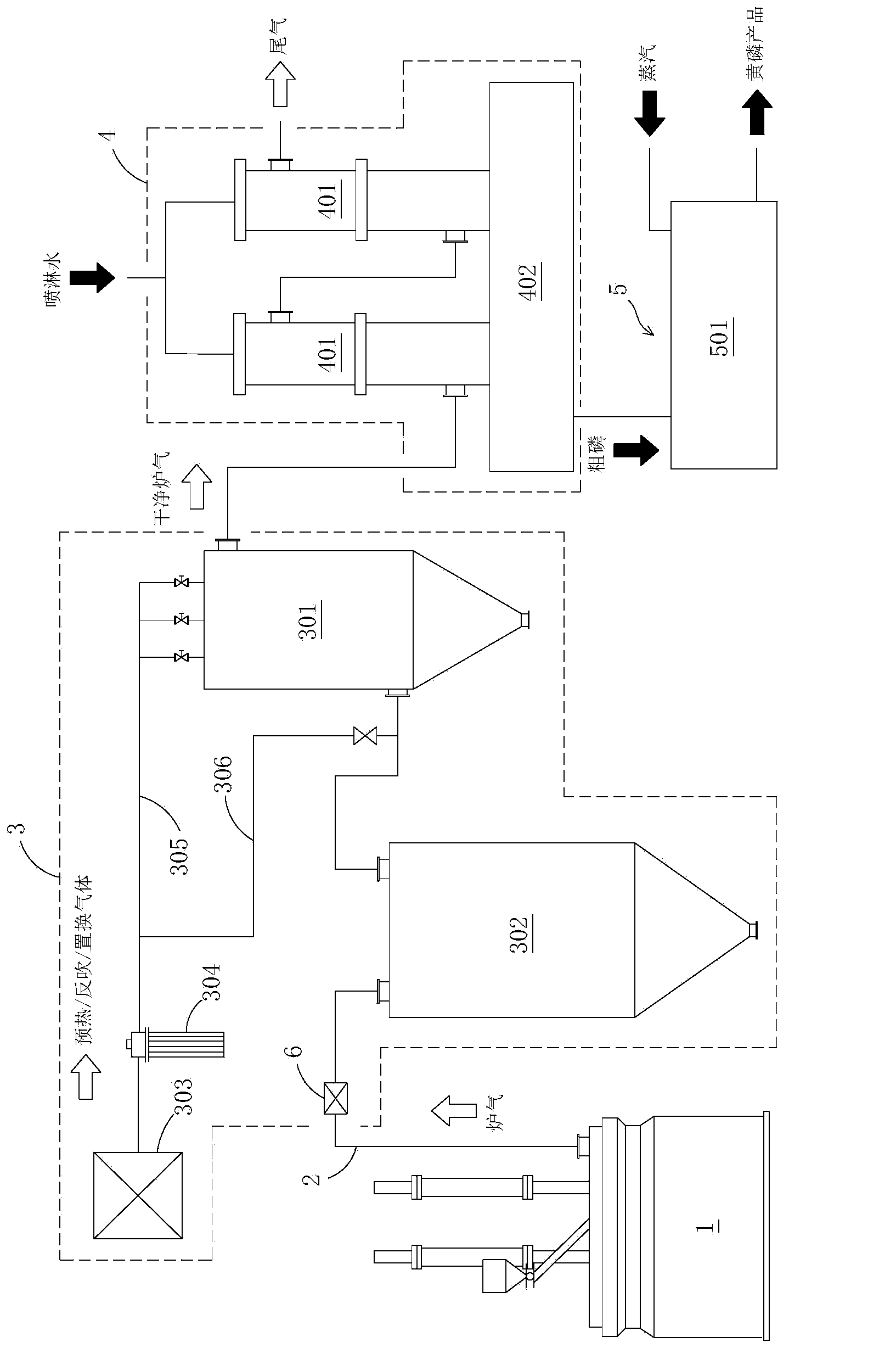
[0073] A multi-electrode phosphorus electric furnace with a transformer capacity of 15000KVA is used. Add 50 tons of mixed material to the electric furnace 1 continuously for reaction. At the same time, start the gas supply device 303 and the heater 304. The high-temperature inert preheating gas passes through the second output pipe 306 and enters the filtered furnace gas inlet pipe from the filter 301. device 301, so as to preheat the sintered inorganic porous material membrane filter element (FeAl intermetallic compound porous material membrane filter element) in the filter 301 to 187.5° C., and then close the valve on the second output pipe 306 . Thereafter, the furnace gas discharged from the electric furnace 1 is introduced into the dry dust removal system 3 through the exhaust pipe 2 , and the furnace gas is heated by the heat exchange device 6 during the process. The heated furnace gas discharged from the electric furnace 1 first enters the mechanical dust collector 302...

Embodiment 2

[0075] After the end of embodiment 1, directly adopt its equipment to continue embodiment 2. The second batch of 50 tons of mixed material was continuously fed into the electric furnace 1 for reaction, and at the same time, switched to another refining pot 501 . The furnace gas discharged from the electric furnace 1 is introduced into the dry dust removal system 3 through the exhaust pipe 2 , and the furnace gas is heated by the heat exchange device 6 during the process. The heated furnace gas discharged from the electric furnace 1 first enters the mechanical dust collector 302 through the exhaust pipe 2 for primary dust removal and purification, and then enters the filter 301 for secondary dust removal and purification. The temperature of the furnace gas to be filtered is detected on the inlet pipe of the furnace gas to be filtered by the filter 301 and is kept at about 250° C. The filter 301 starts an online backflush every 600s. During the backflush, the inert backflush ga...

Embodiment 3

[0077] After the end of embodiment 2, directly adopt its equipment to continue embodiment 3. The third batch of 50 tons of mixed material was continuously fed into the electric furnace 1 for reaction, and at the same time, switched to another refining pot 501 . The furnace gas discharged from the electric furnace 1 is introduced into the dry dust removal system 3 through the exhaust pipe 2 , and the furnace gas is heated by the heat exchange device 6 during the process. The heated furnace gas discharged from the electric furnace 1 first enters the mechanical dust collector 302 through the exhaust pipe 2 for primary dust removal and purification, and then enters the filter 301 for secondary dust removal and purification. The temperature of the furnace gas to be filtered is detected on the inlet pipe of the furnace gas to be filtered by the filter 301 and is kept at about 300° C. The filter 301 starts an online backflush every 600s. During the backflush, the inert backflush gas...


PUM

PropertyMeasurementUnit
solid containing ratioaaaaaaaaaa

Abstract

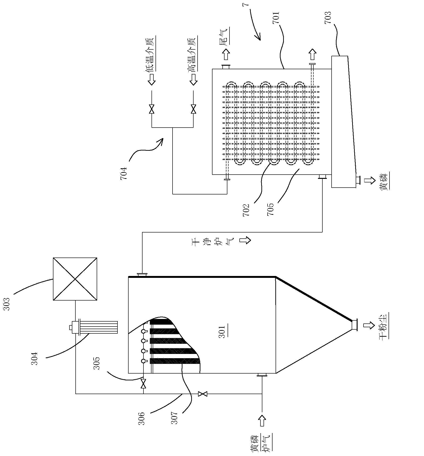
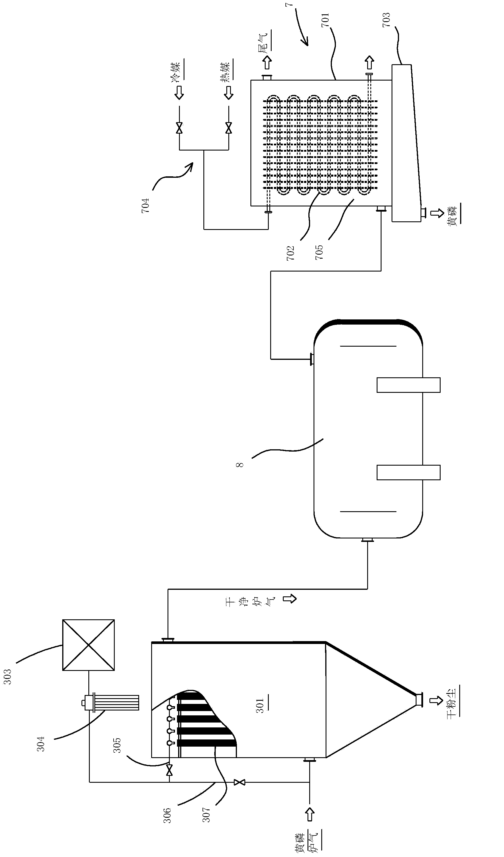
The invention discloses a method and equipment for recovering yellow phosphorus from an electric furnace phosphorus-producing furnace gas without adopting a spray cooling mode in condensation of the electric furnace phosphorus-producing furnace gas, and a special phosphorus collecting device, so as to solve the common problem caused by the spray cooling mode at present. The method comprises the following steps: 1) dedusting and purifying the electric furnace phosphorus-producing furnace gas by using a dry-type dedusting system, so that the solid content of the electric furnace phosphorus-producing furnace gas achieves below 10-50mg / m<3>; 2) conveying the purified furnace gas to a phosphorus collecting device, wherein the phosphorus collecting device comprises a heat exchange chamber and a recuperator; the heat exchange chamber is formed by a shell; and the recuperator is arranged inside the heat exchange chamber; 3) leading in a low-temperature medium to an internal flow path of the recuperator, wherein the low-temperature medium and the furnace gas carry out non-mixing heat transfer under isolation of the recuperator, so that the yellow phosphorus is condensed and separated out and greatly attached on the surface of the recuperator, and the heat-exchange exhaust is discharged out of the phosphorus collecting device; 4) leading in a high-temperature medium for replacing the low-temperature medium to the internal flow path of the recuperator.

Description

technical field [0001] The invention relates to a method, equipment and a special phosphorus collecting device for recovering yellow phosphorus from the furnace gas for producing phosphorus in an electric furnace. Background technique [0002] The electric furnace yellow phosphorus production process for industrial application is divided into the production process using large-scale self-baked electrode phosphorus electric furnace and the production process using multi-electrode phosphorus electric furnace. Although the two processes are different in the type and scale of the electric furnace, the requirements for the treatment of raw materials into the furnace, and the dust removal measures for the furnace gas, the main process is basically the same, that is, the mixture of phosphate rock, silica and coke in proportion. The material is fed into the electric furnace, and the mixture in the electric furnace undergoes a reduction reaction to generate furnace gas. The furnace g...

Claims


Application Information

Patent Timeline
Patent Type & Authority Applications(China)
IPC IPC(8): C01B25/047
CPCC01B25/047B01D53/002B01D53/229B01J19/088B01J2219/0805B01J2219/0879C01B25/027
Inventor 高麟汪涛郭定江
Owner CHENGDU INTERMENT TECH
Learn More