Method for operating a partially closed, turbocharged gas turbine cycle, and gas turbine system for carrying out the method

a gas turbine and cycle technology, applied in the direction of machines/engines, hot gas positive displacement engine plants, combustion engines, etc., can solve the problems of high loss, poor performance of part-load efficiency, and high temperature of the hot gas temperature acting on the turbin

Inactive Publication Date: 2005-06-07
ALSTOM TECH LTD
View PDF19 Cites 37 Cited by
  • Summary
  • Abstract
  • Description
  • Claims
  • Application Information

AI Technical Summary

Benefits of technology

[0018]A preferred configuration of the gas turbine system according to the invention is distinguished by the fact that a precooler is arranged between the entry to the compressor of the gas turbine and the low-pressure-side exit from the recuperator, that the first exhaust-gas turbocharger can be driven by an auxiliary machine, in particular in the form of an electrical machine connected to the grid system via converters, and that a bypass valve is arrang

Problems solved by technology

Since gas turbines designed in this way have at most moderately cooled turbines, the hot-gas temperature which acts on the turbine and is generated by the combustion of a fuel in the combustion chamber arranged between compressor and turbine cannot meet the very high standard set by modern gas turbine construction.
Gas turbines constructed in this way result in a poor performance with regard to part-load efficiency, since the radial compressors used in turbochargers do not allow the intake mass flow to be controlled unless the throttling met

Method used


Image

  • Method for operating a partially closed, turbocharged gas turbine cycle, and gas turbine system for carrying out the method
  • Method for operating a partially closed, turbocharged gas turbine cycle, and gas turbine system for carrying out the method
  • Method for operating a partially closed, turbocharged gas turbine cycle, and gas turbine system for carrying out the method

Examples


Embodiment Construction

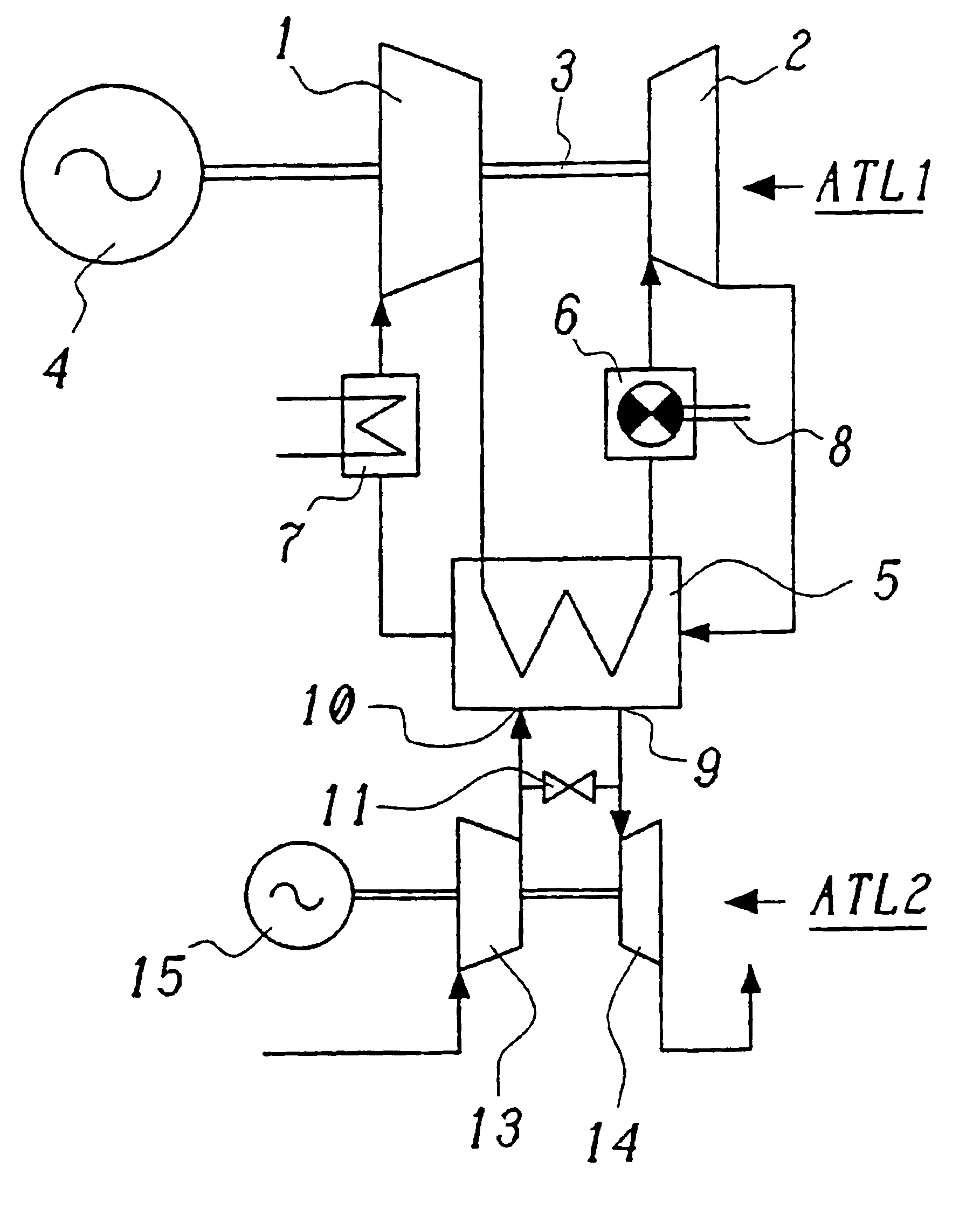
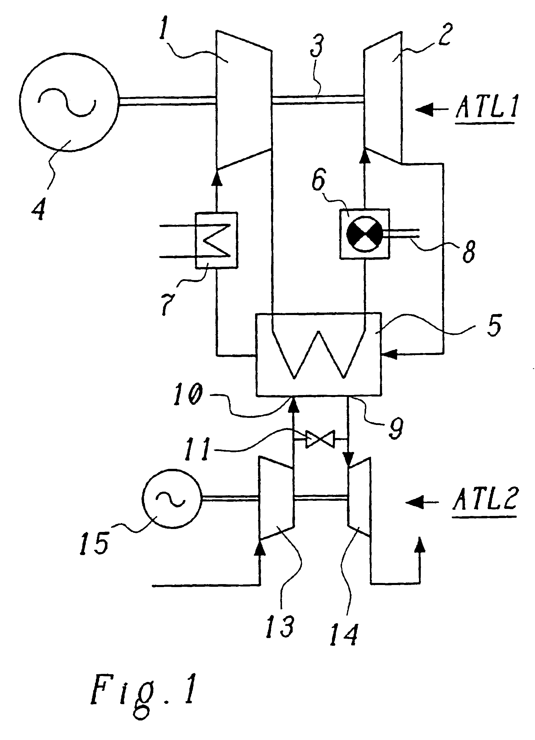
[0024]Referring now to the drawings, wherein like reference numerals designate identical or corresponding parts throughout the several views, FIG. 1 shows a simplified circuit diagram of a partially closed, turbocharged gas turbine cycle or system in accordance with a first exemplary embodiment of the invention with two exhaust-gas turbochargers. A gas turbine in the form of a first exhaust-gas turbocharger ATL1 has a compressor 1 and a turbine 2 on a common shaft 3 connected to a generator 4. The combustion air compressed by the compressor 1 is used in a combustion chamber 6 for combustion of a fuel which is supplied via a fuel feed 8, and the hot fuel gases are then expanded in the turbine 2 so as to perform work. The exhaust gas is returned from the exit of the turbine 2, via the low-pressure side of a recuperator 5 and a precooler 7, to the entry to the compressor 1. The gas turbine cycle which is formed as a result via the recuperator 5 and the precooler 7 is, however, at most ...


PUM


Abstract

A gas turbine system includes a gas turbine (1, 2, 3) having a compressor (1) and a turbine (2), which via a common shaft (3) drive a generator (4), and a combustion chamber (6), the exit of which is connected to the entry to the turbine (2) of the gas turbine (1, 2, 3), has a fuel feed (8) and receives combustion air from the exit of the compressor (1) of the gas turbine (1, 2, 3) via the high-pressure side of a recuperator (5), the exit of the turbine (2) and the entry to the compressor (1) of the gas turbine (1, 2, 3) being connected via the low-pressure side of the recuperator (5), and a first exhaust-gas turbocharger (ATL2) which sucks in air being connected to different locations (9, 10) of the low-pressure side of the recuperator (4) via the exit of its compressor (13) and the entry to its turbine (14).

Description

[0001]This application claims priority to German application no. 103 07 374.4, filed 21 Feb. 2003, the entirety of which is incorporated by reference herein.BACKGROUND OF THE INVENTION[0002]1. Field of the Invention[0003]The present invention deals with the field of gas turbine technology. It relates to a method for operating a partially closed, turbocharged gas turbine cycle, and to a gas turbine system for carrying out the method.[0004]2. Discussion of Background[0005]It is known that gas turbines for performing work can be constructed on the basis of turbochargers, as are used, for example, to turbocharge internal combustion engines. One such example is the microturbines (of type MT100) which have been available for some years from ABB-Energie-Services, with an electrical power of 100 kW, which are intended to serve as small combined heat and power generation installations (cf. Schweizerische Technische Zeitschrift STZ No. 4 / 2002, pages 38 to 40 or ABB Review 3 / 2000, pp. 22-30).[...

Claims


Application Information

Patent Timeline
IPC IPC(8): F02C1/08F02C1/00F02C3/00F02C7/08F02C6/18F02C3/34F02C6/00
CPCF02C1/08F02C3/34F02C6/18F02C7/08F02C6/003Y02E20/14F02C3/085
Inventor FRUTSCHI, HANS ULRICH
Owner ALSTOM TECH LTD
Why Eureka
Try Eureka